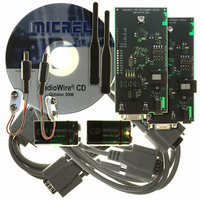
MICRF505DEV1 Micrel Inc, MICRF505DEV1 Datasheet

MICRF505DEV1
Specifications of MICRF505DEV1
Available stocks
Related parts for MICRF505DEV1
MICRF505DEV1 Summary of contents
Page 1
User Manual for Development System MICRF505 MICRF506 MICRF600 MICRF610 MICRF620 Micrel Norway AS Strandveien 13 * 1366 LYSAKER * Norway Tel: + Fax: + ...
Page 2
MICRFXXX: User Manual for Development System, FW v.4 Table of contents: 1. Introduction................................................................................................................. 2 2. Development Board Inputs/Outputs ........................................................................... 5 2.1. Summary of DIP-Switch Setting ........................................................................ 6 3. Getting Started ............................................................................................................ Test Modes............................................................................................................ 8 5. 2-way Link ...
Page 3
MICRFXXX: User Manual for Development System, FW v.4 1. Introduction This document, “MICRFXXX User Manual for Development System” describes the features of the development system for MICRFXXX, where XXX = 505, 506, 600, 610 or 620. The development system is ...
Page 4
MICRFXXX: User Manual for Development System, FW v.4 Outline of this document: Following this introduction, an overview of the board’s inputs/outputs is given. Then a Get-started chapter is included, and the different modes of operation are described. An overview of ...
Page 5
MICRFXXX: User Manual for Development System, FW v.4 Development System Features: • Pre-programmed frequencies: • MICRF505: 25 frequencies, f0=903MHz, f1=904MHz, … f24=927 MHz • MICRF506: 4 frequencies, f0=433.4MHz, f1=433.7MHz, f2=434.1MHz, f3=434.4MHz • MICRF600: 25 frequencies, f0=903.25MHz, f1=924.25MHz, … f24=927.25MHz • ...
Page 6
MICRFXXX: User Manual for Development System, FW v.4 2. Development Board Inputs/Outputs Please observe: The MICRF505 or -506, -600, -610 or -620 is mounted. The user I/Os are equal for all parts. DTE_RTS jumper DTE_CTS jumper DTE_RX jumper RS232 connector ...
Page 7
MICRFXXX: User Manual for Development System, FW v.4 2.1. Summary of DIP-Switch Setting To select mode of operation, bring DIP-switches ON or OFF according to the table below. The modes of operation (described in detail in the following sections) are: ...
Page 8
MICRFXXX: User Manual for Development System, FW v.4 3. Getting Started Before power-up of the development board: • Get familiar with the inputs/outputs (refer to “Development Board Inputs/Outputs”) • Select mode of operation via DIP-switches • If Byte Transfer Mode ...
Page 9
MICRFXXX: User Manual for Development System Test Modes In RF Test Modes, only 1 frequency is used. If not changed via the PC program, the frequency is: MICRF505: 915.00MHz MICRF506: 433.40MHz MICRF600: 915.25MHz MICRF610: 868.307692MHz MICRF620: ...
Page 10
MICRFXXX: User Manual for Development System, FW v.4 Combination #2, Transmit 1010… : The board will enter transmit mode and transmit a 1010… pattern. This can be combined with Combination #1 (Receive mode) to test range and error rate. Combination ...
Page 11
MICRFXXX: User Manual for Development System, FW v.4 All I/O pins of the on-board micro are tristated. New in v.4: None of the MCU’s IOs are set as output at power-on, if this combination is selected. That is: The User ...
Page 12
MICRFXXX: User Manual for Development System, FW v.4 5. 2-way Link Test Mode DIP-switch setting: Combin. # DIP1 DIP2 1 ON OFF 2 ON OFF Note: This mode is changed in version 4. Please refer to “Summary of DIP-Switch Setting”. ...
Page 13
MICRFXXX: User Manual for Development System, FW v.4 • Slave has to transmit ack correctly, and finally, • Master has to receive ack correctly – only then is LED1 set ON. A new message is transmitted every 100 msec (approximately). ...
Page 14
MICRFXXX: User Manual for Development System, FW v.4 6. Interface in Byte Transfer Modes In “Simple” or “Advanced” Byte Transfer Mode: Interface to the board in the following way. Select interface: • Insert the 4 jumpers ( ...
Page 15
MICRFXXX: User Manual for Development System, FW v.4 Maximum number of bytes to transmit in one “data frame” bytes. The board will tell user to “stop enter bytes” by setting CTS inactive when the “bytes-from-user buffer” holds 64 ...
Page 16
MICRFXXX: User Manual for Development System, FW v.4 Example, how to use Simple Byte Transfer Mode: User A (connected to board A) wants to transfer 6 bytes (= “Hello!”). User B (connected to board B) receives the bytes. User A: ...
Page 17
MICRFXXX: User Manual for Development System, FW v.4 8. Advanced Byte Transfer Mode DIP-switch setting: Combin. # DIP1 DIP2 1 OFF OFF 2 OFF OFF Make sure one board is master and one is slave. This mode of operation has ...
Page 18
MICRFXXX: User Manual for Development System, FW v.4 Automatic hopping between frequencies is implemented. For MICRF505/MICRF600: To meet the FCC part 15.247 regulations. The units will jump approx. 10 times/second: For the MICRF506, -610 and -620: less than 25 frequencies ...
Page 19
MICRFXXX: User Manual for Development System program “ RF TestBench” The PC program is referred to as “RF TestBench”. The RF TestBench can be used without the development board. It can be used to calculate fields ...
Page 20
MICRFXXX: User Manual for Development System both “Complete” and “Quick” windows are open: Changes in one window are reflected in the other. • To transfer a control word to the development board from “Quick Setup” or ...
Page 21
MICRFXXX: User Manual for Development System, FW v.4 10. Firmware change/upgrade The development boards are equipped with a socket for ICSP (in-circuit serial programming). Through ICSP possible to download new firmware into the micro controller. The download feature ...
Page 22
MICRFXXX: User Manual for Development System, FW v.4 11. Changes in this Firmware Version V4 2005 06 21 PKB • Included 610 and 620 Modules • Link test payload 5 bytes • Previous Link Test still available • Read DIPs ...


