MICRF505DEV1 Micrel Inc, MICRF505DEV1 Datasheet - Page 4
MICRF505DEV1
Manufacturer Part Number
MICRF505DEV1
Description
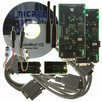
KIT DEV RADIOWIRE 850-950MHZ
Manufacturer
Micrel Inc
Series
RadioWire®r
Type
Transceiver, ISMr
Specifications of MICRF505DEV1
Frequency
850MHz ~ 950MHz
For Use With/related Products
MICRF505
Lead Free Status / RoHS Status
Lead free / RoHS Compliant
Other names
576-1606
Available stocks
Company
Part Number
Manufacturer
Quantity
Price
Company:

Part Number:
MICRF505DEV1
Manufacturer:
Micrel Inc
Quantity:
135


MICRFXXX: User Manual for Development System, FW v.4
Outline of this document:
Following this introduction, an overview of the board’s inputs/outputs is given. Then a
Get-started chapter is included, and the different modes of operation are described. An
overview of how to program/update the firmware is also included. Finally, a list of
changes for this firmware version is given.
Purpose of the Development system:
The development system provides hands-on experience with the MICRFXXX
transceiver. The user can use the included firmware (the program used in the micro
controller) and hardware, or make a new program and flash it into the micro controller.
That is, the user can use the boards both to evaluate the MICRFXXX, and as an aid in the
development of a radio communication system.
A separate PC program is available. Through this program, it is possible to set the
programming word for the MICRFXXX (both the frequency dividers and the control bits
can be set). This program is referred to as “RF TestBench”. Please observe: It is possible
to read out the firmware version of the development boards via RF TestBench.
Main modes of operation of the development system:
• RF Test Modes. The user can test the RF properties of the transceiver. It is possible
• 2-way Link-Test Mode. In this mode of operation, one board is “Master” and
• Simple Byte Transfer Mode. In this mode, the user can enter a number of bytes into
• Advanced Byte Transfer Mode. In this mode of operation, one board is “Master”
Micrel Norway, Oslo Norway
to transmit a 1010… pattern or a random pattern, transmit a carrier or to stay in
receive mode, searching for a 1010… pattern. In addition, the user can select to
bypass the MCU completely, and control the RF part via header pins.
another board is “Slave”. Messages (5 printable ascii characters) are transmitted back
and forth between the two boards. This mode is useful when testing radio
communication in different environments, testing antennas, testing encapsulation etc.
16-bit CRC is implemented. A LED (“LED1”) indicates link OK.
a development board. The board will then transmit the bytes. If no user-bytes are
entered, the board will search for RF messages, and, if found, output the message to
the user. 16-bit CRC is implemented (messages received through RF are only given to
user if the CRC is OK). A 64-byte deep buffer is implemented for both RX and TX.
Only 1 frequency is used.
and another board is “Slave”. Operates like the “Simple Byte Transfer Mode”, except:
When transmitting user data, the board will construct a frame by adding frame type,
frame ID and sync info. Automatic frequency hopping is implemented. ARQ
(Automatic Repeat reQuest), CRC and duplicate control are implemented as well.
“Master” is responsible for maintaining the link (by transmitting “timestamps”). If
“Slave” is reset or gets out of sync, it requests a “timestamp” from Master.
3
Related parts for MICRF505DEV1
Image
Part Number
Description
Manufacturer
Datasheet
Request
R

Part Number:
Description:
Manufacturer:
Micrel Inc
Datasheet:
Part Number:
Description:
Manufacturer:
Micrel Inc
Datasheet:
Part Number:
Description:
Manufacturer:
Micrel Inc
Datasheet:
Part Number:
Description:
Manufacturer:
Micrel Inc
Datasheet:
Part Number:
Description:
Manufacturer:
Micrel Inc
Datasheet:
Part Number:
Description:
Manufacturer:
Micrel Inc
Datasheet:
Part Number:
Description:
Manufacturer:
Micrel Inc
Datasheet:
Part Number:
Description:
Manufacturer:
Micrel Inc
Datasheet:
Part Number:
Description:
Manufacturer:
Micrel Inc
Datasheet:
Part Number:
Description:
Manufacturer:
Micrel Inc
Datasheet:
Part Number:
Description:
Manufacturer:
Micrel Inc
Datasheet:
Part Number:
Description:
Manufacturer:
Micrel Inc
Datasheet:
Part Number:
Description:
Manufacturer:
Micrel Inc
Datasheet:
Part Number:
Description:
Manufacturer:
Micrel Inc
Datasheet: