EVB71102B-433-FSK-C Melexis Inc, EVB71102B-433-FSK-C Datasheet - Page 3
EVB71102B-433-FSK-C
Manufacturer Part Number
EVB71102B-433-FSK-C
Description
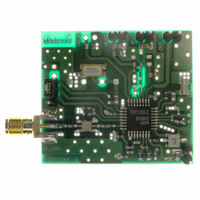
EVALUATION BOARD TH71102 RECEIVR
Manufacturer
Melexis Inc
Type
Receiver, ASK/FSKr
Specifications of EVB71102B-433-FSK-C
Rohs Status
RoHS non-compliant
Frequency
433MHz
For Use With/related Products
TH71102
Other names
EVB71102-433-FSK
EVB71102-433-FSK
EVB71102-433.92F
EVB71102-433.92F
EVB71102B-433FSKC
EVB71102-433-FSK
EVB71102-433.92F
EVB71102-433.92F
EVB71102B-433FSKC


1
1.1
With the TH71102 receiver chip, various circuit configurations can be arranged in order to meet a number of
different customer requirements. For FSK reception the IF tank used in the phase coincidence demodulator
can be constituted by an external ceramic discriminator. In ASK configuration, the RSSI signal is fed to an
ASK detector, which is constituted by the operational amplifier.
The superheterodyne configuration is double conversion where MIX1 and MIX2 are driven by the internal
local oscillator signals LO1 and LO2, respectively. This allows a high degree of image rejection, achieved in
conjunction with an RF front-end filter. Efficient RF front-end filtering is realized by using a SAW, ceramic or
helix filter in front of the LNA and by adding an LC filter at the LNA output.
A single-conversion variant, called TH71101, is also available. Both Receiver ICs have the same die. At the
TH71101 the second mixer MIX2 operates as an amplifier.
The TH71102 receiver IC consists of the following building blocks:
1.2
1) at 4 kbps NRZ, BER = 3⋅10
2) at 4 kbps NRZ, BER = 3⋅10
39012 71102 01
Rev. 012
PLL synthesizer (PLL SYNTH) for generation of the first and second local oscillator signals LO1 and LO2,
parts of the PLL SYNTH are: the high-frequency VCO1, the feedback dividers DIV_8 and DIV_2,
a phase-frequency detector (PFD) with charge pump (CP) and a crystal-based reference oscillator (RO)
Low-noise amplifier (LNA) for high-sensitivity RF signal reception
First mixer (MIX1) for down-conversion of the RF signal to the first IF (IF1)
Second mixer (MIX2) for down-conversion of the IF1 to the second IF (IF2)
IF amplifier (IFA) to amplify and limit the IF2 signal and for RSSI generation
Phase coincidence demodulator (DEMOD) with third mixer (MIX3) to demodulate the IF signal
Operational amplifier (OA) for data slicing, filtering and ASK detection
Bias circuitry for bandgap biasing and circuit shutdown
Input frequency range: 260 MHz to 510 MHz
Power supply range: 2.3 V to 5.5 V @ ASK
Temperature range: -40 °C to +85 °C
Standby current: 50 nA
Operating current: 6.5 mA @ low gain mode
Sensitivity: -110 dBm @ ASK 1)
Range of first IF1: 10 MHz to 80 MHz
filter loss
Theory of Operation
General
EVB Technical Data Overview
For more detailed information, please refer to the latest TH71102 data sheet revision
-104 dBm @ FSK 2)
8.2 mA @ high gain mode
2.7 V to 5.5 V @ FSK
-3
-3
, 180 kHz IF filter BW, incl. 3 dB SAW front-end-filter loss
, ± 20 kHz FSK deviation, 180 kHz IF filter BW, incl. 3 dB SAW front-end-
Page 3 of 14
Range of first IF2: 400 kHz to 22 MHz
Maximum input level: -10 dBm @ ASK
Image rejection: > 65 dB (e.g. with 433.92 MHz
SAW front-end filter and at 10.7 MHz IF2)
Spurious emission: < -70 dBm
Input frequency acceptance range: up to ±100 kHz
RSSI range: 70 dB
FSK deviation range: ±2.5 kHz to ±80 kHz
Evaluation Board Description
315/433MHz Receiver
0 dBm @ FSK
EVB71102
EVB Description
April/08
Related parts for EVB71102B-433-FSK-C
Image
Part Number
Description
Manufacturer
Datasheet
Request
R

Part Number:
Description:
EVALUATION BOARD TH71102 RECEIVR
Manufacturer:
Melexis Inc
Datasheet:

Part Number:
Description:
EVALUATION BOARD TH71102 RECEIVR
Manufacturer:
Melexis Inc
Datasheet:
Part Number:
Description:
Evaluation Board For Th71102
Manufacturer:
Melexis Company
Datasheet:
Part Number:
Description:
315/433MHz Receiver Evaluation Board Description
Manufacturer:
MELEXIS [Melexis Microelectronic Systems]
Datasheet:

Part Number:
Description:
IC LATCH CMOS MP TSOT23-3
Manufacturer:
Melexis Inc
Datasheet:

Part Number:
Description:
IC LATCH CMOS MP TSOT23-3
Manufacturer:
Melexis Inc
Datasheet:
Part Number:
Description:
IC HALL EFFECT SW TSOT-23
Manufacturer:
Melexis Inc
Datasheet:

Part Number:
Description:
IC HALL EFFECT SWITCH TSOT-23
Manufacturer:
Melexis Inc
Datasheet: