1321XEVK Freescale Semiconductor, 1321XEVK Datasheet - Page 66
1321XEVK
Manufacturer Part Number
1321XEVK
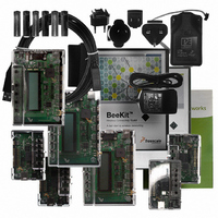
Description
KIT EVALUATION FOR 1321X
Manufacturer
Freescale Semiconductor
Type
Zigbeer
Specifications of 1321XEVK
Frequency
2.4GHz
Wireless Frequency
2.4 GHz
Modulation
DSSS OQPSK
Security
128 bit AES
Operating Voltage
2 VDC to 3.4 VDC
Operating Temperature Range
- 40 C to + 85 C
For Use With/related Products
MC1321x
Lead Free Status / RoHS Status
Contains lead / RoHS non-compliant


7.3
Figure 35
printed copper F antenna is used for low cost. Only the RFIN port of the MC1321x is required because the
differential port is bi-directional and uses the on-chip T/R switch. Matching to near 50 Ohms is
accomplished with L1, L2, L3, and the traces on the PCB. A balun transforms the differential signal to
single-ended to interface with the F antenna.
The proper DC bias to the RFIN_x (PAO_x) pins is provided through the balun. The CT_Bias pin provides
the proper bias voltage point to the balun depending on operation, that is, CT_Bias is at VDDA voltage for
transmit and is at ground for receive. CT_Bias is switched between these two voltages based on the
operation. Capacitor C2 provides some high frequency bypass to the dc bias point. The L3/C1 network
provides a simple bandpass filter to limit out-of-band harmonics from the transmitter.
66
•
U1
MC1321x
RFIN_M
CT_Bias
RFIN_P
PAO_M
PAO_P
GPIO1
When the MCU is used in low power modes, be sure that all unused IO are programmed properly
for low power operation (typically best case is as outputs in the low state). The MC1321x is
commonly used with the Freescale MC9S08GT/GB 8-bit devices. For these MCUs:
— Use only STOP2 and STOP3 modes (not STOP1) with these devices where the GPIO states are
— As stated above all unused GPIO should be programmed as outputs low for lowest power and
— The MCU has IO signals that are not pinned-out on the package. These signals must also be
44
39
38
36
35
34
RF Single Port Application with an F Antenna
shows a typical single port RF application topology in which part count is minimized and a
retained. The MCU must retain control of the MC1321x IO during low power operation.
no floating inputs.
initialized (even though they cannot be used) to prevent floating inputs.
Passive component values can vary as a function of circuit board layout as
required to obtain best matching and RF performance.
L1
1.5nH
L4
1.5nH
Figure 35. RF Single Port Application with an F-Antenna
L2
3.9nH
MC13211/212/213 Technical Data, Rev. 1.8
C2
10pF
3
2
4
Z1
LDB212G4005C-001
1
5
6
NOTE
L3
3.9nH
C1
1.0pF
R2
0R
Not Mounted
R1
0R
Freescale Semiconductor
2
3
4
5
ANT1
F_Antenna
J1
SMA_edge_Receptacle_Female
Related parts for 1321XEVK
Image
Part Number
Description
Manufacturer
Datasheet
Request
R

Part Number:
Description:
Manufacturer:
Freescale Semiconductor, Inc
Datasheet:
Part Number:
Description:
Manufacturer:
Freescale Semiconductor, Inc
Datasheet:
Part Number:
Description:
Manufacturer:
Freescale Semiconductor, Inc
Datasheet:
Part Number:
Description:
Manufacturer:
Freescale Semiconductor, Inc
Datasheet:
Part Number:
Description:
Manufacturer:
Freescale Semiconductor, Inc
Datasheet:
Part Number:
Description:
Manufacturer:
Freescale Semiconductor, Inc
Datasheet:
Part Number:
Description:
Manufacturer:
Freescale Semiconductor, Inc
Datasheet:
Part Number:
Description:
Manufacturer:
Freescale Semiconductor, Inc
Datasheet:
Part Number:
Description:
Manufacturer:
Freescale Semiconductor, Inc
Datasheet:
Part Number:
Description:
Manufacturer:
Freescale Semiconductor, Inc
Datasheet:
Part Number:
Description:
Manufacturer:
Freescale Semiconductor, Inc
Datasheet:
Part Number:
Description:
Manufacturer:
Freescale Semiconductor, Inc
Datasheet:
Part Number:
Description:
Manufacturer:
Freescale Semiconductor, Inc
Datasheet:
Part Number:
Description:
Manufacturer:
Freescale Semiconductor, Inc
Datasheet:
Part Number:
Description:
Manufacturer:
Freescale Semiconductor, Inc
Datasheet: