MDEV-916-ES-RS232 Linx Technologies Inc, MDEV-916-ES-RS232 Datasheet - Page 3
MDEV-916-ES-RS232
Manufacturer Part Number
MDEV-916-ES-RS232
Description
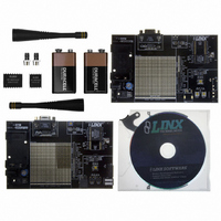
KIT MASTER DEV 916MHZ ES RS232
Manufacturer
Linx Technologies Inc
Series
ESr
Type
Transmitterr
Specifications of MDEV-916-ES-RS232
Frequency
916MHz
Product
RF Development Tools
Maximum Frequency
916 MHz
Supply Voltage (max)
9 V
Lead Free Status / RoHS Status
Lead free / RoHS Compliant
For Use With/related Products
ES Series RF Modules - 916MHz
Lead Free Status / Rohs Status
Lead free / RoHS Compliant
Other names
MDEV-916-ES-232
MDEV-916-ES-232
MDEV-916-ES-232


USING THE DEVELOPMENT BOARDS
TROUBLESHOOTING
THE PROTOTYPING AREA
Page 4
Figure 3: The Development Board Prototyping Area
• Check the battery to make sure it is not dead.
• Make sure that the antenna is connected.
• Make sure that the jumpers are set correctly.
• Ensure that the Baud Rate Selector switches are set the same on both boards.
• Create and learn a new address.
All of the module’s connections are made available to the designer via the wire-
wrap header (TS1 / TS2). Jumper shunts have been provided. These shunts are
placed across adjacent pins to control the routing of TX and RX data. After
unpacking the development system, attach an antenna to each board, install the
supplied 9V battery, and turn on the power switches. The development board is
now ready for use.
If the boards fail to work out of the box, then try the following:
If all of these appear to be in order, then you can call 800-736-6677 or e-mail
techsupport@linxtechnologies.com for technical support.
In addition to their evaluation functions, the boards may also be used for actual
product development. They feature a prototyping area to facilitate the addition of
application-specific circuitry. The prototyping area is the same on both boards
and contains a large area of plated through-holes so that external circuitry can
be placed on the board. The holes are set at 0.100” on center with a 0.040”
diameter, making it easy to add most industry-standard SIP and DIP packages
to the board. This circuitry can be interfaced with the ES transmitter or receiver
through the breakout header to the right. At the bottom of this area is a row
connected to the 5V power supply and at the top is a row connected to ground.
NOTE: The on-board 5-volt regulator has approximately 500mA of headroom available for
additional circuitry. If added circuitry requires a higher current, the user must add an
additional regulator to the prototype area or power the board from an external supply.
Ground Bus
+5 Volt Bus
Regulator
USING THE SIMPLEX ENCODER / DECODER SECTION
The transmitter board features an MS Series remote control encoder with two
push buttons and the receiver board features a decoder with a relay output and
a buzzer. When a button is pressed on the transmitter board, the status of both
buttons is captured and encoded into a data stream for transmission. The data
recovered by the receiver is decoded and the decoder's data lines are set to
replicate the status of the encoder, driving either the buzzer or the relay.
To activate this area of the board, the module data line must be routed to the
encoder / decoder. Configure the transmitter board for encoding and
transmission by placing a jumper across TX DATA and ENCODER and across
TX PDN and PDN ENC on header TS1. Configure the receiver board for
reception and decoding by placing a jumper across RX DATA and DECODER
on header TS2.
Once the boards have been configured, place the
receiver board on a flat surface and turn it on. Turn
on the transmitter board and press button S0. You
should hear the buzzer on the receiver board
sound. You may now walk away from the receiver
to ascertain the useable range of the link in your
environment.
Button S1 activates the relay on the receiver board.
The relay’s SPST contacts can be connected at J2.
Any device up to 5A at 30VDC / 120VAC may be switched through the relay.
Most commonly, an external siren or light would be connected to aid range
testing if the on-board buzzer is not loud enough.
As you near the maximum range of the link in your area, it is not uncommon for
the signal to cut in and out as you move. This is normal and can result from other
interfering sources or fluctuating signal levels due to multipath effects. This
results in cancellation of the transmitted signal as direct and reflected signals
arrive at the receiver at differient times and phases. The areas in which this
occurs are commonly called “nulls” and simply walking a little farther will often
restore the signal.
To achieve maximum range, keep objects such as your hand away from the
antenna and ensure that the antenna on the transmitter has a clear and
unobstructed line-of-sight path to the receiver board. Range performance is
determined by many interdependent factors. If the range you are able to achieve
is significantly less than specified by Linx for the products you are testing, then
there is likely a problem with either the board or the ambient RF environment in
which the board is operating. First, check the battery, switch positions, and
antenna connection. Next, measure the receiver’s RSSI voltage with the
transmitter turned off to determine if ambient interference is present. If this fails
to resolve the issue, please contact Linx technical support.
Since the evaluation boards are intended for use by design engineers, they are
not FCC certified. The transmitter has been set to approximate legal limits by
resistor R29 so that the range test results will approximate the results from a
well-designed, certified product. For applications where Part 15 limits are not
applicable or output levels can be legally raised, R29 can be changed according
to the graph on Page 3 of the ES Series Transmitter Data Guide.
Figure 4: Jumper Configuration
TS1
TX
PDN ENC
TX PDN
PDN RS232
TX RS232
TX DATA
TX ENCODER
/CLK
/CLK SEL
LO V DET
NC
GND
SQ. DATA
NC
AUDIO REF
AUDIO
RSSI
RX DATA
RX DECODER
RX PDN
RX
TS2
Page 5
Related parts for MDEV-916-ES-RS232
Image
Part Number
Description
Manufacturer
Datasheet
Request
R

Part Number:
Description:
KIT MASTER DEV 916MHZ ES USB
Manufacturer:
Linx Technologies Inc
Datasheet:

Part Number:
Description:
KIT MASTER DEVELP 916MHZ SCS SMD
Manufacturer:
Linx Technologies Inc

Part Number:
Description:
KIT MASTER DEVELOP 916MHZ SC SRS
Manufacturer:
Linx Technologies Inc

Part Number:
Description:
HOLDER BATTERY 20MM COIN CR2032
Manufacturer:
Linx Technologies Inc
Datasheet:

Part Number:
Description:
CONN RPSMA BL CRJA-CPV 8.5" COAX
Manufacturer:
Linx Technologies Inc

Part Number:
Description:
CABLE RG174 RPSMA M/F 8.5"
Manufacturer:
Linx Technologies Inc

Part Number:
Description:
CABLE RG174 SMA M/F 8.5"
Manufacturer:
Linx Technologies Inc

Part Number:
Description:
CABLE RPSMA/SMA 8.5"
Manufacturer:
Linx Technologies Inc

Part Number:
Description:
CABLE MALE-NMALE 8' RG-58 RPSMA
Manufacturer:
Linx Technologies Inc

Part Number:
Description:
CABLE RPSMA/SMA 8.5"
Manufacturer:
Linx Technologies Inc

Part Number:
Description:
MODULE USB LOW SPEED
Manufacturer:
Linx Technologies Inc
Datasheet:

Part Number:
Description:
IC TRANSCODER MT BI-DIR 20-SSOP
Manufacturer:
Linx Technologies Inc
Datasheet:

Part Number:
Description:
IC ENCODER LOW SECURITY 8DIP
Manufacturer:
Linx Technologies Inc
Datasheet:

Part Number:
Description:
IC DECODER MS SERIES 20-SSOP
Manufacturer:
Linx Technologies Inc
Datasheet:
Part Number:
Description:
IC ENCODER MS SERIES 20-SSOP
Manufacturer:
Linx Technologies Inc
Datasheet: