ATAB5429-9-WB Atmel, ATAB5429-9-WB Datasheet - Page 18
ATAB5429-9-WB
Manufacturer Part Number
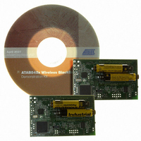
ATAB5429-9-WB
Description
KIT DEMO 915MHZ BLACKBIRD
Manufacturer
Atmel
Type
Transceiver, UHFr
Specifications of ATAB5429-9-WB
Frequency
915MHz
Maximum Frequency
915 MHz
Output Power
0 dBm to 10 dBm
Supply Voltage (max)
6 V
Supply Voltage (min)
3 V
Supply Current
21 mA
Maximum Operating Temperature
+ 85 C
Board Size
2 in x 3.5 in
Minimum Operating Temperature
- 40 C
Product
RF Modules
For Use With/related Products
ATA5429
Lead Free Status / RoHS Status
Lead free / RoHS Compliant
Other names
ATAB-5429-9-WB
ATAB-5429-9-WB
ATAB-5429-9-WB


3.10
3.11
18
Frequency Synthesizer
FSK/ASK Transmission
ATA5423/ATA5425/ATA5428/ATA5429
The synthesizer is a fully integrated fractional-N design with internal loop filters for receive and
transmit mode. The XTO frequency f
The bits FR0 to FR12 in control registers 2 and 3 (see
page
has a phase noise of –111 dBC/Hz at 1 MHz and spurious emissions at FREF of –66 dBC with a
high PLL loop bandwidth allowing the direct modulation of the carrier with 20 Kbit/s Manchester
data. Due to the closed loop modulation any spurious emissions caused by this modulation are
effectively filtered out as can be seen in
a phase noise of –120 dBC/Hz at 1 MHz and spurious emissions of –75 dBC.
The initial tolerances of the crystal oscillator due to crystal tolerances, internal capacitor toler-
ances and the parasitics of the board have to be compensated at manufacturing setup with
control registers 2 and 3 as can be seen in
synthesizer needed for ASK, FSK and receive/transmit switching are calculated internally. The
RF (Radio Frequency) resolution is equal to the XTO frequency divided by 16384 which is
777.1 Hz at 315.0 MHz, 851.1 Hz at 345.0 MHz, 808.9 Hz at 433.92 MHz, 818.6 Hz at
868.3 MHz and 862.6 Hz at 915.0 MHz.
For the multi-channel system the frequency control word FREQ in control registers 2 and 3 can
be programmed in the range of 1000 to 6900, this is equivalent to a programmable tuning range
of ±2.5 MHz hence every frequency within the 315 MHz, 345 MHz, 433 MHz, 868 MHz and
915 MHz ISM bands can be programmed as receive and as transmit frequency, and the position
of channels within these ISM bands can be chosen arbitrarily (see
Care must be taken as to the harmonics of the CLK output signal as well as to the harmonics
produced by a microprocessor clocked with it, since these harmonics can disturb the reception
of signals. In a single-channel system, using FREQ = 3803 to 4053 ensures that harmonics of
this signal do not disturb the receive mode.
Due to the fast modulation capability of the synthesizer and the high resolution, the carrier can
be internally FSK modulated, which simplifies the application of the transceiver. The deviation of
the transmitted signal is ±20 digital frequency steps of the synthesizer which is equal to
±15.54 kHz for 315 MHz, ±17.02 kHz for 345 MHz, ±16.17 kHz for 433.92 MHz, ±16.37 kHz for
868.3 MHz and ±17.25 kHz for 915 MHz.
Due to closed loop modulation with PLL filtering the modulated spectrum is very clean, meeting
ETSI and CEPT regulations when using a simple LC filter for the power amplifier harmonics as it
is shown in
ter of the FSK transmission and the power amplifier is switched on and off to perform the
modulation.
ulation with pseudo-random data with 20 Kbit/s/±16.17 kHz/Manchester and 5 dBm output
power.
40) are used to adjust the deviation of f
Figure 2.2 on page
Figure 3-7 on page 19
8. In ASK mode the frequency is internally connected to the cen-
to
Figure 3-9 on page 20
XTO
Figure 3-9 on page
is the reference frequency FREF for the synthesizer.
Table 4-1 on page
XTO
. In transmit mode, at 433.92 MHz, the carrier
Table 7-7 on page 39
20. In RX mode the synthesizer has
show the spectrum of the FSK mod-
28. The other control words for the
Table
4-1).
and
4841D–WIRE–10/07
Table 7-10 on
Related parts for ATAB5429-9-WB
Image
Part Number
Description
Manufacturer
Datasheet
Request
R

Part Number:
Description:
BOARD BASESTATN UHF RCVR 915MHZ
Manufacturer:
Atmel
Datasheet:

Part Number:
Description:
DEV KIT FOR AVR/AVR32
Manufacturer:
Atmel
Datasheet:

Part Number:
Description:
INTERVAL AND WIPE/WASH WIPER CONTROL IC WITH DELAY
Manufacturer:
ATMEL Corporation
Datasheet:
Part Number:
Description:
Low-Voltage Voice-Switched IC for Hands-Free Operation
Manufacturer:
ATMEL Corporation
Datasheet:
Part Number:
Description:
MONOLITHIC INTEGRATED FEATUREPHONE CIRCUIT
Manufacturer:
ATMEL Corporation
Datasheet:
Part Number:
Description:
AM-FM Receiver IC U4255BM-M
Manufacturer:
ATMEL Corporation
Datasheet:
Part Number:
Description:
Monolithic Integrated Feature Phone Circuit
Manufacturer:
ATMEL Corporation
Datasheet:
Part Number:
Description:
Multistandard Video-IF and Quasi Parallel Sound Processing
Manufacturer:
ATMEL Corporation
Datasheet:
Part Number:
Description:
High-performance EE PLD
Manufacturer:
ATMEL Corporation
Datasheet:
Part Number:
Description:
8-bit Flash Microcontroller
Manufacturer:
ATMEL Corporation
Datasheet:
Part Number:
Description:
2-Wire Serial EEPROM
Manufacturer:
ATMEL Corporation
Datasheet: