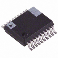
AD607ARSZ-REEL Analog Devices Inc, AD607ARSZ-REEL Datasheet - Page 4

AD607ARSZ-REEL
Manufacturer Part Number
AD607ARSZ-REEL
Description
IC RECEIVER IF SUBSYS LP 20SSOP
Manufacturer
Analog Devices Inc
Datasheet
1.AD607-EBZ.pdf
(24 pages)
Specifications of AD607ARSZ-REEL
Rf Type
Cellular, GSM, CDMA, TDMA, TETRA
Function
Receiver IF Subsystem
Frequency
500MHz
Secondary Attributes
-8dBm Input Third Order Intercept
Package / Case
20-SSOP (0.200", 5.30mm Width)
Frequency Range
400kHz To 12MHz
Supply Voltage Range
2.92V To 5.5V
Rf Ic Case Style
SSOP
No. Of Pins
20
Operating Temperature Range
-40°C To +85°C
Operating Supply Voltage
3V
Operating Temperature (min)
-40C
Operating Temperature (max)
85C
Operating Temperature Classification
Industrial
Lead Free Status / RoHS Status
Lead free / RoHS Compliant
Lead Free Status / RoHS Status
Lead free / RoHS Compliant, Lead free / RoHS Compliant
AD607
Pin
1
2
3
4
5
6
7
8
9
10
11
12
13
14
15
16
17
18
19
20
Mnemonic
FDIN
COM1
PRUP
LOIP
RFLO
RFHI
GREF
MXOP
VMID
IFHI
IFLO
GAIN
COM2
IFOP
DMIP
VPS2
QOUT
IOUT
FLTR
VPS1
Reads
Frequency Detector Input
Common #1
Power-Up Input
Local Oscillator Input
RF “Low” Input
RF “High” Input
Gain Reference Input
Mixer Output
Midsupply Bias Voltage
IF “High” Input
IF “Low” Input
Gain Control Input
Common #2
IF Output
Demodulator Input
VPOS Supply #2
Quadrature Output
In-Phase Output
PLL Loop Filter
VPOS Supply #1
PIN FUNCTION DESCRIPTIONS
MXOP
PRUP
COM1
RFLO
GREF
VMID
FDIN
LOIP
RFHI
20-Lead SSOP (RS-20)
IFHI
PIN CONNECTION
10
1
2
3
4
5
6
7
8
9
(Not to Scale)
TOP VIEW
AD607
–4–
Function
PLL Input for I/Q Demodulator Quadrature Oscillator, ± 400 mV
Drive Required from External Oscillator. Must be biased at V
Supply Common for RF Front End and Main Bias
3 V/5 V CMOS compatible power-up control; logical high =
powered-up; max input level = VPS1 = VPS2.
LO input, ac-coupled ± 54 mV LO input is required (–16 dBm for
50 Ω input termination).
Usually Connected to AC Ground
AC-Coupled, ± 56 mV, Max RF Input for Linear Operation
High Impedance Input, typically 1.5 V, sets gain scaling.
High Impedance, Single-Sided Current Output, ± 1.3 V Max
Voltage Output (± 6 mA Max Current Output)
Output of the Midsupply Bias Generator (VMID = VPOS/2)
AC-Coupled IF Input, ± 56 mV Max Input for Linear Operation
Reference Node for IF Input; Auto-Offset Null
High Impedance Input, 0 V–2 V Using 3 V Supply, Max Gain at
V = 0
Supply Common for IF Stages and Demodulator
Low Impedance, Single-Sided Voltage Output, 5 dBm
(± 560 mV) Max
Signal input to I and Q demodulators has a ± 150 mV max input
at IF > 3 MHz for linear operation; ±75 mV max input at IF < 3 MHz
for linear operation. Must be biased at V
Supply to High Level IF, PLL, and Demodulators
Low Impedance Q Baseband Output; ± 1.23 V Full Scale in 20 kΩ
Min Load; AC-Coupled
Low Impedance I Baseband Output; ± 1.23 V Full Scale in 20 kΩ
Min Load; AC-Coupled
Series RC PLL Loop Filter, Connected to Ground
Supply to Mixer, Low Level IF, PLL, and Gain Control
20
19
18
17
16
15
14
13
12
11
VPS1
FLTR
IOUT
QOUT
VPS2
DMIP
IFOP
COM2
GAIN
IFLO
P
/2.
REV. C
P
/2.


