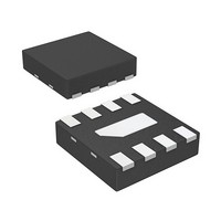
AMMP-6530-TR1 Avago Technologies US Inc., AMMP-6530-TR1 Datasheet - Page 2

AMMP-6530-TR1
Manufacturer Part Number
AMMP-6530-TR1
Description
IC MMIC REJECT MXR 5-30GHZ 8-SMD
Manufacturer
Avago Technologies US Inc.
Series
AMMP-6530r
Datasheet
1.AMMP-6530-TR2.pdf
(11 pages)
Specifications of AMMP-6530-TR1
Frequency
5GHz ~ 30GHz
Function
Mixer
Rf Type
ISM; DBS; VSAT; 802.16/WiMax; WLL; MMDS
Package / Case
8-QFN
Rf Ic Case Style
SMD
No. Of Pins
8
Operating Temperature Range
-55°C To +125°C
Frequency Max
30GHz
Ic Function
Image Reject Mixer
Termination Type
SMD
Supply Voltage Max
0V
Filter Terminals
SMD
Rohs Compliant
Yes
Digital Ic Case Style
SMD
Gain Typ, V/v
-10
Lead Free Status / RoHS Status
Lead free / RoHS Compliant
Lead Free Status / RoHS Status
Lead free / RoHS Compliant, Lead free / RoHS Compliant
Available stocks
Company
Part Number
Manufacturer
Quantity
Price
Part Number:
AMMP-6530-TR1
Manufacturer:
AVAGO/安华高
Quantity:
20 000
AMMP-6530 DC Specifications/Physical Properties
Symbol
I
V
T
T
Note:
1. Ambient operational temperature T
AMMP-6530 Typical Performance
Symbol
F
F
F
P
CG
RL_RF
RL_LO
RL_IF
IR
LO-RF Iso.
LO-IF Iso.
RF-IF Iso.
IIP3
P-1
NF
Notes:
2. Small/Large signal data measured in a fully de-embedded test fixture form T
3. Specifications are derived from measurements in a 50Ω test environment.
AMMP-6530 RF Specifications in Drain Pumped Test Configuration
(T
Notes:
4. Pre-assembly into package performance verified 100% on-wafer.
5. This final package part performance is verified by a functional test correlated to actual performance.
6. The external 90 degree hybrid coupler is from M/A-COM: PN 2032-6344-00. Frequency 1.0– 2.0 GHz.
7. 100% on-package test is done at RF frequency = 21 GHz, LO frequency = 23 GHz (IF frequency = 2 GHz)
2
g
mins
maxs
Symbol
CG
IR
RF
LO
IF
g
LO
A
= 25°C, V
g
= -1.0V, P
Parameters and Test Conditions
Gate Supply Current
(under any RF power drive and temperature)
Gate Supply Operating Voltage
Min. Ambient Operating Temp.
Max. Ambient Operating Temp.
Parameters and Test Conditions
FF Frequency Range
LO Frequency Range
IF Frequency Range
LO Port Pumping Power
RF to IF Conversion Gain
RF Port Return Loss
LO Port Return Loss
IF Port Return Loss
Image Rejection Ratio
LO to RF Port Isolation
LO to IF Port Isolation
RF to IF Port Isolation
Input IP3, Fdelta=100 MHz,
Prf = -10 dBm, Plo = 10 dBm
Input Port Power at 1dB gain
compression point, Plo=+10 dBm
Noise Figure
Conversion Gain
Image Rejection Ratio
Parameters and Test Conditions
LO
≥+10 dBm, Z
o
=50 Ω)
A
[7]
[2, 3]
=25°C unless otherwise noted.
(T
A
= 25°C, V
g
[1]
= -1V, IF frequency = 1 GHz, Z
Units
GHz
GHz
GHz
dBm
dB
dB
dB
dB
dB
dB
dB
dB
dBm
dBm
dB
Units
dB
dB
[4, 5, 6]
Units
mA
V
°C
°C
A
= 25°C.
Down Conversion
>10
-10
5
10
10
15
22
25
15
18
8
10
Min
-12.5
o
=50 Ω)
Min.
-55
Gate Pumped
5 – 30
5 – 30
DC – 5
Up Conversion
>0
-15
5
10
10
15
25
25
15
—
—
—
Typ.
-8
20
Typ.
0
-1V
Drain Pumped
5 – 30
5 – 30
DC – 5
Down Conversion
>10
-8
10
5
10
15
22
25
15
10
0
12
Max
Max.
+125


