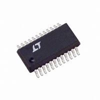
LT5500EGN Linear Technology, LT5500EGN Datasheet - Page 8

LT5500EGN
Manufacturer Part Number
LT5500EGN
Description
IC RECEIVER FRONT END 24-SSOP
Manufacturer
Linear Technology
Datasheet
1.LT5500EGN.pdf
(12 pages)
Specifications of LT5500EGN
Frequency
1.8GHz ~ 2.7GHz
Applications
HS Wireless LAN, Wireless Local Loop
Current - Receiving
23mA
Data Interface
PCB, Surface Mount
Antenna Connector
PCB, Surface Mount
Voltage - Supply
1.8 V ~ 5.25 V
Operating Temperature
-40°C ~ 85°C
Package / Case
24-SSOP
Pin Count
24
Screening Level
Industrial
Lead Free Status / RoHS Status
Contains lead / RoHS non-compliant
Features
-
Sensitivity
-
Memory Size
-
Data Rate - Maximum
-
Modulation Or Protocol
-
Lead Free Status / Rohs Status
Not Compliant
Available stocks
Company
Part Number
Manufacturer
Quantity
Price
Company:
Part Number:
LT5500EGN
Manufacturer:
LT
Quantity:
5 549
Part Number:
LT5500EGN
Manufacturer:
LINEAR/凌特
Quantity:
20 000
Part Number:
LT5500EGN#PBF
Manufacturer:
LINEAR/凌特
Quantity:
20 000
Part Number:
LT5500EGN#TRPBF
Manufacturer:
LINEAR/凌特
Quantity:
20 000
APPLICATIONS
LT5500
An IF transformer can be used to create a single-ended
output. The additional discrete components necessary to
achieve a 50Ω match are tabulated in Figure 3. Alterna-
tively, the discrete solution shown in Figure 4 can be used
to perform differential to single-ended conversion. For
best LO and RF signal suppression at the IF output, a
transformer should be used. If it is desirable to reduce the
gain of the mixer, a resistor between the IF outputs can be
used.
8
IF OUTPUT
Figure 4. Alternative Mixer IF Output Matching
50Ω
APPLICATION DEPENDENT
COMPONENT VALUES
RF INPUT
C14
C17
C23
C4
L4
L2
L3
L9
L7
T1
280MHz IF OUTPUT
12
U
1.8GHz
4.7nH
4.7nH
220pF
5.6nH
1.8pF
12nH
L10
10pF
15nH
TC8-1 MINI-CIRCUITS
IF
+
INFORMATION
LT5500
U
V
C12
Figure 3. Simplified Test Schematic for 1.8GHz and 2.5GHz Applications
CC
2.5GHz
2.7nH
4.7nH
1.8nH
220pF
2.7nH
1.5pF
10pF
L11
IF
100pF
–
W
13
IF OUTPUT
RF INPUT
5500 F04
IF OUTPUT
L10, L11
C12
C14
U
L7
280MHz
3.3pF
2.2pF
27nH
V
4.7nH
CC
L5
ENABLE
*
•
100pF
T1
EN
V
MIX_GND
LNA_IN
GND
LNA_GND
CC
•
LO Buffer
The LO inputs can be driven either differentially or single
ended. A single-ended configuration is shown along with
example component values in Figure 3. Optionally, the LO
can be driven differentially as shown in Figure 5.
BIAS
V
Figure 5. Optional Transformer-Based Differential LO Drive
CC
IF
LT5500
C2
100pF
+
LO
IF
RF
IF
5500 F03
LNA_OUT
–
*REFER TO FIGURE 6 FOR POWER SUPPLY
MIX_IN
PINS BYPASSING RECOMMENDATION
100pF
LT5500
LO
LO
GS
–
+
LO
LO
LO INPUT
SELECT
–
+
GAIN
C17
TX1
C4
L3
19
18
L9
L4
L3
TX1
V
4:1
TOKO-BF4
CC
2.22GHz
3.3nH
C23
L2
5500 F05
100pF
L3
LO INPUT
MIXER RF
INPUT
RF OUT
LO INPUT
100pF
5500f


