MC33591FTA Freescale Semiconductor, MC33591FTA Datasheet - Page 9
MC33591FTA
Manufacturer Part Number
MC33591FTA
Description
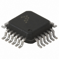
IC RF RECEIVER 315,434MHZ 24LQFP
Manufacturer
Freescale Semiconductor
Datasheet
1.MC33591MOD315.pdf
(28 pages)
Specifications of MC33591FTA
Frequency
315MHz, 434MHz
Sensitivity
-105dBm
Data Rate - Maximum
11 kBaud
Modulation Or Protocol
FSK, OOK
Applications
General Data Transfer
Current - Receiving
5.7mA
Data Interface
PCB, Surface Mount
Antenna Connector
PCB, Surface Mount
Voltage - Supply
1.9 V ~ 3.6 V
Operating Temperature
-40°C ~ 85°C
Package / Case
24-LQFP
Lead Free Status / RoHS Status
Contains lead / RoHS non-compliant
Features
-
Memory Size
-
Available stocks
Company
Part Number
Manufacturer
Quantity
Price
Company:

Part Number:
MC33591FTAE
Manufacturer:
Freescal
Quantity:
18


CLOCK GENERATOR
SERIAL INTERFACE
If the SPI is not used, a Power On Reset (POR) sets ROMEO2 to operate correctly in a default configuration.
MISO lines. The master and slave devices are capable of exchanging a byte of information during a sequence of
eight clock cycles. Since SCLK is generated by the master device, this line is an input on a slave device.
The MISO line is configured as an input in a master device and as an output in a slave device. The MOSI line is
configured as an output in a master device and as an input in a slave device. The MISO and MOSI lines transfer
serial data in one direction with the most significant bit sent first. Data are captured on falling edges of SCLK.
Data are shifted out on rising edge of SCLK. When no data are output, SCLK and MOSI force a low level. Using
Motorola acronyms, this means that the clock phase and polarity control bits of the microcontroller SPI have to be
CPOL= 0 and CPHA=1.
the microcontroller is the master node providing clock information on SCLK input, control and configuration bits
on the MOSI line. If the default configuration is not the desired one, the microcontroller (MCU) can change it by
writing into the configuration registers. The configuration registers can also be read back to check their contents.
Configuration registers cannot be addressed separately, the whole configuration has to be sent as a 3x8
bitstream. The contents are written out as a 24-bit serial data stream. Transmissions which are not multiple of 24
Typical crystal frequencies are:
ROMEO2 and the microcontroller communicate through a Serial Peripheral Interface (SPI). It enables:
The interface is operated by the 3 following input/output pins:
The master clock is used to synchronise data movement both in and out of the device through its MOSI and
In configuration mode, as long as a low level is applied on RESETB (see state machine on figure 14 page 13),
MOTOROLA
- 9.864375MHz for 315MHz band,
- 13.580625MHz for 434MHz band.
- the microcontroller to set and check ROMEO2 configuration,
- ROMEO2 to send the received data.
- Serial Clock SCLK,
- Master Output Slave Input MOSI,
- Master Input Slave Output MISO.
Phase Frequency Detector
UHF Oscillator
¸ 32
Freescale Semiconductor, Inc.
For More Information On This Product,
Figure 11: Clock generation diagram
MC33591 Technical Data
Go to: www.freescale.com
Reference
XTAL
315MHz band
434MHz band
IF Filter Reference Clock
& Clock Recovery
¸ 8
¸ 11
CLOCK GENERATOR
9
Related parts for MC33591FTA
Image
Part Number
Description
Manufacturer
Datasheet
Request
R


Part Number:
Description:
Manufacturer:
Freescale Semiconductor, Inc
Datasheet:
Part Number:
Description:
Manufacturer:
Freescale Semiconductor, Inc
Datasheet:
Part Number:
Description:
Manufacturer:
Freescale Semiconductor, Inc
Datasheet:
Part Number:
Description:
Manufacturer:
Freescale Semiconductor, Inc
Datasheet:
Part Number:
Description:
Manufacturer:
Freescale Semiconductor, Inc
Datasheet:
Part Number:
Description:
Manufacturer:
Freescale Semiconductor, Inc
Datasheet:
Part Number:
Description:
Manufacturer:
Freescale Semiconductor, Inc
Datasheet:
Part Number:
Description:
Manufacturer:
Freescale Semiconductor, Inc
Datasheet:
Part Number:
Description:
Manufacturer:
Freescale Semiconductor, Inc
Datasheet:
Part Number:
Description:
Manufacturer:
Freescale Semiconductor, Inc
Datasheet:
Part Number:
Description:
Manufacturer:
Freescale Semiconductor, Inc
Datasheet:
Part Number:
Description:
Manufacturer:
Freescale Semiconductor, Inc
Datasheet:
Part Number:
Description:
Manufacturer:
Freescale Semiconductor, Inc
Datasheet:
Part Number:
Description:
Manufacturer:
Freescale Semiconductor, Inc
Datasheet: