RN-41 Roving Networks Inc, RN-41 Datasheet - Page 15
RN-41
Manufacturer Part Number
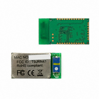
RN-41
Description
MODULE BLUETOOTH W/ANT CLASS1
Manufacturer
Roving Networks Inc
Specifications of RN-41
Frequency
2.4GHz
Data Rate - Maximum
2Mbps
Modulation Or Protocol
Bluetooth v2.0+EDR, Class 1 & 2
Applications
Bluetooth v2.0
Power - Output
15dBm
Sensitivity
-80dBm
Voltage - Supply
3 V ~ 3.6 V
Current - Receiving
35mA
Current - Transmitting
65mA
Data Interface
PCB, Surface Mount
Memory Size
8MB Flash
Antenna Connector
PCB, Surface Mount
Operating Temperature
-40°C ~ 85°C
Package / Case
Module
Wireless Frequency
2.402 GHz to 2.48 GHz
Interface Type
UART, USB, PCM
Data Rate
721 Kbps to 2 Mbps
Modulation
FHSS, GFSK
Operating Voltage
3.3 V
Antenna
Chip Antenna
Board Size
13.2 mm x 25.8 mm x 2.05 mm
Operating Temperature Range
- 40 C to + 85 C
Security
128 bit Encryption
Lead Free Status / RoHS Status
Lead free / RoHS Compliant
Lead Free Status / RoHS Status
Lead free / RoHS Compliant, Lead free / RoHS Compliant
Other names
740-1007


4.4
www.rovingnetworks.com
Z
&
+
GPIO Commands
Each GPIO command takes 16 bit parameter made up of 2 bytes, a mask to specify the GPIO number and value for each
command. The first byte, the mask, determines which GPIO is affected by the command, and the second byte is the
value to set.
There are two registers used to control the GPIO, the first is a direction register. This controls whether the GPIO is an
input or an output. The second register is the value to apply to the GPIO if set to an output, or is the value of the built-in
weak pull-up resistor if the GPIO is set to an input. These settings are immediate, and do not survive a power cycle.
Examples: S@,8080
Power-up values: These 2 registers will apply the direction and values upon each subsequent power-up:
Examples: S%,0101
Multiple bits can be set with a single command, any bits with a mask of 0 are left unaffected.
Some GPIO are read at power-up time to perform certain functions, so care must be taken when manipulating them.
GPIO3 and GPIO6 are used to automatically set master mode, and auto discovery. If it is desired to use these GPIO for
other purposes at power-up, a special command must be used to disable their being sensed at power-up time. This
command is “SQ,4<cr>” this will set a flag in a stored register that is read at power-up. The Power-up settings for the
GPIO can also be viewed using the “O” (other settings) command.
809 University Avenue
S&,8080
S&,8000
S^,0303
PARAMETER[15:0] = MASK[7...0]<<8 || VALUE[7..0]
CMD
@
%
&
^
*
drives GPIO-0 high, and pulls up GPIO-1.
sets GPIO-0 to an output on power-up
drives GPIO-7 high
drives GPIO-7 low
sets GPIO-7 to an output
Enters low power deep sleep mode (<2ma) when NOT connected. Can only be
exited by power cycling the device or toggling the RESET pin on the module
(causing a HARD reset). For more on managing power see section 5.
Returns the value of the DIP switches on Serial adapters and USB-X dongle, or value
of GPIO 3,4,6,7 on other modules.
Local echo ON/OFF, when turned on in command mode all characters typed will be
echoed to the output. Typing + a second time will turn OFF local echo.
•
Los Gatos, CA 95032
<hexword>
<hexword>
<hexword>
<hexword>
<hexword>
VALUE
Store powerup direction bits for GPIO
Store powerup values for GPIO
~ 15 ~
Set values for PIO8,9,10,11
•
Set direction bits for GPIO
Tel (408) 395-6539
Set values for GPIO
DESCRIPTION
rn-bluetooth-um Version 4.77 1/24/2011
Advanced User Manual
• info@RovingNetworks.com
Related parts for RN-41
Image
Part Number
Description
Manufacturer
Datasheet
Request
R

Part Number:
Description:
MODULE BLUETOOTH V2.1+EDR
Manufacturer:
Roving Networks Inc
Datasheet:

Part Number:
Description:
ANTENNA 2.4GHZ 4 INCH W/RPSMA
Manufacturer:
Roving Networks Inc
Datasheet:

Part Number:
Description:
MODULE WIFLY 802.11B 1/4 WV-WIRE
Manufacturer:
Roving Networks Inc
Datasheet:

Part Number:
Description:
ANTENNA 2.4GHZ 4" SMA MALE
Manufacturer:
Roving Networks Inc
Datasheet:

Part Number:
Description:
ANTENNA 2.4GHZ STUBBY 1"
Manufacturer:
Roving Networks Inc
Datasheet:

Part Number:
Description:
ANTENNA 2.4GHZ 2.5" R/A SMA MALE
Manufacturer:
Roving Networks Inc
Datasheet:

Part Number:
Description:
ADAPTER BLUETOOTH FRFLY SRL FEML
Manufacturer:
Roving Networks Inc
Datasheet:

Part Number:
Description:
ADAPTER BLUETOOTH FRFLY SRL MALE
Manufacturer:
Roving Networks Inc
Datasheet:

Part Number:
Description:
ADAPTER BLUETOOTH FIREFLY RS422
Manufacturer:
Roving Networks Inc
Datasheet:

Part Number:
Description:
ANTENNA 2.4GHZ RPSMA
Manufacturer:
Roving Networks Inc
Datasheet:

Part Number:
Description:
ADAPTER BLUETOOTH FRFLY SRL MALE
Manufacturer:
Roving Networks Inc
Datasheet:

Part Number:
Description:
ADAPTER BLUETOOTH FRFLY SRL MALE
Manufacturer:
Roving Networks Inc
Datasheet:

Part Number:
Description:
SUPERMODULE BLUETOOTH CHIP ANT
Manufacturer:
Roving Networks Inc
Datasheet:

Part Number:
Description:
MODULE SOCKET BLUETOOTH CLASS1
Manufacturer:
Roving Networks Inc
Datasheet:
Part Number:
Description:
MODULE BLUETOOTH V2.1+EDR
Manufacturer:
Roving Networks Inc
Datasheet: