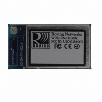
RN-131G Roving Networks Inc, RN-131G Datasheet - Page 7

RN-131G
Manufacturer Part Number
RN-131G
Description
MODULE WIFLY GSX 802.11 SMD
Manufacturer
Roving Networks Inc
Datasheet
1.RN-131G.pdf
(11 pages)
Specifications of RN-131G
Frequency
2.4GHz
Data Rate - Maximum
1Mbps
Modulation Or Protocol
802.11 b/g
Applications
Home Automation, Security
Power - Output
18dBm
Sensitivity
-85dBm
Voltage - Supply
3 V ~ 3.7 V
Current - Receiving
40mA
Current - Transmitting
210mA
Data Interface
PCB, Surface Mount
Memory Size
8Mb Flash, 128kB RAM
Antenna Connector
On-Board, Chip, U.FL
Operating Temperature
-40°C ~ 85°C
Package / Case
Module
Wireless Frequency
2.4 GHz
Modulation
DSSS
Security
WEP 128, WPA2-PSK
Operating Voltage
3.3 V
Antenna
Chip, U.FL
Operating Temperature Range
- 40 C to + 85 C
Lead Free Status / RoHS Status
Lead free / RoHS Compliant
Lead Free Status / RoHS Status
Lead free / RoHS Compliant, Lead free / RoHS Compliant
Other names
740-1028
Design Concerns
1. Minimizing radio interference. When integrating the WiFly
2. Proper grounding. For the module antenna to function pins
3. Solder Reflow. Reflow temperature must not exceed 220C.
module with on board chip antenna make sure the area
around the chip antenna end the module protrudes at least
6mm from the mother board PCB and any metal enclosure. If
this is not possible use the on board U.FL connector to route
to an external Antenna.
The 8.5 mm area under the antenna end of the module
should be keep clear of metallic components, connectors,
vias, traces and other materials that can interfere with the
radio signal.
36- to 44 must be connected to GND. We suggest you place
module such that 0.5mm of theses pads is exposed. This
provides access for soldiering pins 36 through 44 from below
and provides ample clearance of the antenna from the PCB.
To reflow solder the RN-131G and RN-131C module onto a
PCB Roving recommends a RoHS compliant solder paste
equivalent to the NIHON ALMIT paste or OMNIX OM-310
solder paste from Alpha metals.
NOTE: Use no clean Flux, Do NOT water wash!
Note also, that the temperature profile is based on the IC level and other components level only (without the
shield can). So if we go on module perspective, above 245C profile should be acceptable.
In fact the module temperature profile specifications tells, that you should be able to go beyond 240C (from
220C[60secs] to 250C[10secs]). The module temperature profile diagram is shown below.
www.rovingnetworks.com
809 University Avenue
•
Los Gatos, CA 95032
~ page 7 ~
•
Tel (408) 395-6539
Keep metallic components,
connectors,,vias and traces,
away from antenna area
8.5 mm
RN-131G & RN-131C
• info@RovingNetworks.com
RN-131-DS v2.5 12/2/2010
Mother Board
For RN-131
Bottom view
RN131G
Top view
30 mm
For proper antenna
Performance pins 36
through 44 must be
grounded
8.5 mm
6 mm


