DNT2400P RFM, DNT2400P Datasheet
DNT2400P
Specifications of DNT2400P
Available stocks


Related parts for DNT2400P


DNT2400P Summary of contents
Page 1
... Sym Notes Minimum Typical 2409 FSK/MSK 38.4, 115.2, 200 and 500 -104 -96 - DNT2400P - U.FL Coaxial Connector DNT2400C - U.FL Connector or PCB Pad Point-to-Point, Point-to-Multipoint CSMA and TDMA DEVELOPMENT KIT (Info Click here) DNT2400 Low Cost Transceiver Module with I/O Maximum Units 2467 ...
Page 2
... Remote, 9.6 kb/s Continuous Data Stream Remote, 115.2 kb/s Continuous Data Stream Sleep Current DNT2400C Mounting DNT2400P Mounting Operating Temperature Range Operating Relative Humidity Range, Non-condensing Notes: 1. PWM is set with an 8-bit value. DAC resolution is limited to 7 bits by residual ripple at output of low-pass filter. ...
Page 3
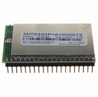
... The radio is available in two mounting configurations. www.RFM.com E-mail: info@rfm.com ©2009 by RF Monolithics, Inc. Figure 1 The DNT2400C is designed for solder reflow mounting, and the DNT2400P is designed for plug-in connector mounting. DNT2400 Firmware The DNT2400 firmware can operate using either TDMA or CSMA channel access modes. TDMA supports remotes with rapid, deterministic channel latency ...
Page 4
... O hopping pattern and logic low on a base station when at least one remote is connected to it. 27 RSVD - Reserved pin. Leave unconnected. 28 RSVD - Reserved pin. Leave unconnected. 29 RSVD - Reserved pin. Leave unconnected. www.RFM.com E-mail: info@rfm.com ©2009 by RF Monolithics, Inc. Description DNT2400 - 08/12/09 Page ...
Page 5
... RF ground for the DNT2400C only. Connect to the host circuit board ground plane. DNT2400C RFIO Stripline The DNT2400C has a U.FL coaxial connector mounted near pad 42 for antenna connection (see Antenna Con- nector discussion below also possible to connect an antenna using a stripline from pad 42 important www.RFM.com E-mail: info@rfm.com ©2009 by RF Monolithics, Inc. Description Figure 2 ...
Page 6
... Note that other circuit board traces should be spaced away from the stripline to prevent signal coupling, as shown in Figure 4. The stripline trace should be kept short to minimize its insertion loss. www.RFM.com E-mail: info@rfm.com ©2009 by RF Monolithics, Inc. Trace Separation from ...
Page 7
... Note that other circuit board traces should be spaced away from the stripline to prevent signal cou- pling, as shown in Figure 4. The stripline trace should be kept short to minimize its insertion loss. Note: Specifications subject to change without notice. www.RFM.com E-mail: info@rfm.com ©2009 by RF Monolithics, Inc. Figure 6 ...