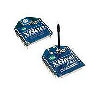
XBP24-ASI-001 Digi International, XBP24-ASI-001 Datasheet - Page 32

XBP24-ASI-001
Manufacturer Part Number
XBP24-ASI-001
Description
MODULE XBEE 1MW W/RPSMA
Manufacturer
Digi International
Series
XBEE-PRO™r
Specifications of XBP24-ASI-001
Frequency
2.4GHz
Data Rate - Maximum
250kbps
Modulation Or Protocol
802.15.4
Applications
Home/Building Automation, Industrial Control, ZigBee™
Power - Output
18dBm
Sensitivity
-100dBm
Voltage - Supply
2.8 V ~ 3.4 V
Current - Receiving
55mA
Current - Transmitting
215mA @ 3.3V
Data Interface
PCB, Through Hole
Antenna Connector
RP-SMA
Operating Temperature
-40°C ~ 85°C
Package / Case
Module
Lead Free Status / RoHS Status
Lead free / RoHS Compliant
Memory Size
-
Lead Free Status / Rohs Status
Lead free / RoHS Compliant
Available stocks
Company
Part Number
Manufacturer
Quantity
Price
Part Number:
XBP24-ASI-001J
Manufacturer:
XBEE
Quantity:
20 000
* Firmware version in which the command was first introduced (firmware versions are numbered in hexadecimal notation.)
Serial Interfacing
Table 3‐05. XBee‐PRO Commands ‐ Serial Interfacing
* Firmware version in which the command was first introduced (firmware versions are numbered in hexadecimal notation.)
I/O Settings
Table 3‐06. XBee‐PRO Commands ‐ I/O Settings (sub‐category designated within {brackets})
XBee®/XBee‐PRO® RF Modules ‐ 802.15.4 ‐ v1.xEx [2009.09.23]
AT
Command
BD
RO
AP (v1.x80*)
NB
PR (v1.x80*)
AT
Command
D8
D7 (v1.x80*)
D6 (v1.x80*)
Command
Category
Serial
Interfacing
Serial
Interfacing
Serial
Interfacing
Serial
Interfacing
Serial
Interfacing
Command
Category
I/O Settings
I/O Settings
I/O Settings
Name and Description
Interface Data Rate. Set/Read the serial interface data rate for communications
between the RF module serial port and host.
Request non-standard baud rates with values above 0x80 using a terminal window.
Read the BD register to find actual baud rate achieved.
Packetization Timeout. Set/Read number of character times of inter-character delay
required before transmission. Set to zero to transmit characters as they arrive instead of
buffering them into one RF packet.
API Enable. Disable/Enable API Mode.
Parity. Set/Read parity settings.
Pull-up Resistor Enable. Set/Read bitfield to configure internal pull-up resistor status
for I/O lines
Bitfield Map:
Bit set to “1” specifies pull-up enabled; “0” specifies no pull-up
Name and Description
DI8 Configuration. Select/Read options for the DI8 line (pin 9) of the RF module.
DIO7 Configuration. Select/Read settings for the DIO7 line (pin 12) of the RF module.
Options include CTS flow control and I/O line settings.
DIO6 Configuration. Select/Read settings for the DIO6 line (pin 16) of the RF module.
Options include RTS flow control and I/O line settings.
© 2009 Digi Internatonal, Inc.
bit 0 - AD4/DIO4 (pin11)
bit 1 - AD3 / DIO3 (pin17)
bit 2 - AD2/DIO2 (pin18)
bit 3 - AD1/DIO1 (pin19)
bit 4 - AD0 / DIO0 (pin20)
bit 5 - RTS / AD6 / DIO6 (pin16)
bit 6 - DTR / SLEEP_RQ / DI8 (pin9)
bit 7 - DIN/CONFIG (pin3)
Parameter Range
0 - 7 (standard baud rates)
0x80 - 0x3D090
(non-standard baud rates up to
250 Kbps)
0 - 0xFF [x character times]
0 - 2
control characters)
0 - 4
0 - 0xFF
Parameter Range
0 - 1
(1,2,4 & 5 n/a)
0 - 1
6 = RS485 Tx Enable Low
7 = RS485 Tx Enable High
0 - 1
0 = 1200 bps
1 = 2400
2 = 4800
3 = 9600
4 = 19200
5 = 38400
6 = 57600
7 = 115200
0 =Disabled
1 = API enabled
2 = API enabled (w/escaped
0 = 8-bit no parity
1 = 8-bit even
2 = 8-bit odd
3 = 8-bit mark
4 = 8-bit space
0 = Disabled
3 = DI
0 = Disabled
1 = CTS Flow Control
2 = (n/a)
3 = DI
4 = DO low
5 = DO high
0 = Disabled
1 = RTS flow control
2 = (n/a)
3 = DI
4 = DO low
5 = DO high
Default
3
3
0
0
0xFF
Default
0
1
0
32


