370100620 Sigma Designs Inc, 370100620 Datasheet
370100620
Specifications of 370100620


Related parts for 370100620


370100620 Summary of contents
Page 1
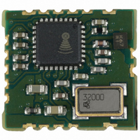
The ZM2102 Z-Wave Module communication module that uses the unlicensed Short-Range- Device (SRD) frequency band of 868.42MHz in Europe and 908.42MHz in US. The ZM2102 is dedicated for wireless control and monitoring of residential products like lighting and appliance control, ...
Page 2
DSH10229-11-11 1 PRODUCT DESCRIPTION ...................................................................................................................3 1.1 Overview................................................................................................................................................3 1.2 Signal Description..................................................................................................................................4 1.3 RF Front-End.........................................................................................................................................5 1.3.1 RF input/output ...........................................................................................................................5 1.3.2 Antenna Matching.......................................................................................................................5 1.4 Z-Wave Module Programming ..............................................................................................................6 2 SPECIFICATIONS ................................................................................................................................7 2.1 ZW0201 Specification ...........................................................................................................................7 2.2 ZW0201 Single Chip Peripherals ..........................................................................................................7 2.3 RF ...
Page 3
DSH10229-11-11 1 PRODUCT DESCRIPTION 1.1 Overview The ZM2102 Z-Wave Module is a fully integrated module containing all the HW and SW required to Z-Wave enable OEM products. The ZM2102 Z-Wave Module contains the Z-Wave ZW0201 Single Chip, System Crystal, RF ...
Page 4
DSH10229-11-11 1.2 Signal Description ZM2102 10 US 908.42MHz 11 0310 Name Notch # I/O ADC[3:0] 10, 13, I 14, 15 GND 1, 6, 12, Power 16, 17 INT[1: I/O ...
Page 5
DSH10229-11-11 Name Notch # I/O RESET_N I/O RXD 10 I/O 1 SCK 8 I/O TRIAC 13 I/O TXD 15 I/O VCC 11 Power ZEROX 14 I/O 1. Please note that the SPI interface (MISO, MOSI and ...
Page 6
DSH10229-11-11 different antennas is given as well as their pro’s and con’s. In the case the antenna is not 50ohm a matching network must be implemented between the ZM2102 Z-Wave Module and the antenna. The matching network can for example ...
Page 7
DSH10229-11-11 2 SPECIFICATIONS 2.1 ZW0201 Specification MCU Description MCU Type Optimized 8-bit 8051 MCU core. MCU speed 16 MHz (integrated clock divider, external crystal frequency is 32MHz) Flash 32kbyte. Programmed through the SPI interface. SRAM 2kbyte SRAM (CPU) 256byte MCU ...
Page 8
DSH10229-11-11 2.4 Electrical Specification The “Absolute Maximum Ratings” specifies the conditions in which the ZM2102 Z-Wave Module is guaranteed not to be damaged but correct operations are not guaranteed. Exceeding the “Absolute Maximum Ratings” may destroy the ZM2102 Z-Wave Module. ...
Page 9
DSH10229-11-11 2.5 Physical Specification Physical Specification Description Size 12.5mm. x 13.6mm. x 2.4mm (0.492” x 0.535” x 0.094”) Weight 7g (with shield) 5g (without shield) Castellation Notches 18 2.6 Process Specification Specification Description MSL-3 Moisture Level Verification tested according to ...
Page 10
DSH10229-11-11 2.7 Recommended PCB Footprint Outline 14.30 mm. 10.15 mm. 7 8.65 mm. 8 7.15 mm. 9 5.65 mm 4.15 mm. 0 mm. 1.10mm. Ø0.55mm. Figure 5 Recommend ZM2102 PCB footprint Outline Zensys A/S ZM2102 Z-Wave Module Datasheet ...
Page 11
DSH10229-11-11 2.8 Recommended Reflow Profile Figure 6 Recommended Reflow Temperature Profile 2.9 Application PCB Layout Recommendation 2.9.1 Supply Voltage As the ZM2102 Z-Wave Module contains a RF transceiver good supply voltage decoupling is important. Two decoupling capacitors should be placed ...
Page 12
DSH10229-11-11 2.9.2 Ground Plane In order to minimize any noise coupling from noisy signals (typically power products recommended to insert as much ground cobber below the ZM2102 Z-Wave Module as possible on the Application PCB. 2.9.3 Antenna Interconnection ...
Page 13
DSH10229-11-11 3 SOFTWARE 3.1 SPI Interface The signals ‘P1.2/MISO’, ‘P1.4/SCK’ and ‘P1.3/MOSI’ signals are in some SW API’s used by the protocol to store Routing Tables and HomeID in an external EEPROM. When these SW API’s are used, the Application ...
Page 14
DSH10229-11-11 4 REFERENCES Always refer to latest document revision. [1] Zensys, DSH10560, Datasheet, ZW0201 with Developers Kit v4.1x [2] Zensys, APL10312, Application Note, Programming the 200-Series Z-Wave Single Chip Flash [3] Zensys, INS10247, Instruction, Z-Wave ZW0102/ZW0201 Application Programming Guide [4] ...