CM1400DU-24NF Powerex Inc, CM1400DU-24NF Datasheet - Page 2
CM1400DU-24NF
Manufacturer Part Number
CM1400DU-24NF
Description
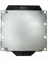
IGBT MOD DUAL 1200V 1400A MEGA
Manufacturer
Powerex Inc
Series
IGBTMOD™r
Type
IGBT Moduler
Datasheet
1.CM1400DU-24NF.pdf
(4 pages)
Specifications of CM1400DU-24NF
Configuration
Half Bridge
Voltage - Collector Emitter Breakdown (max)
1200V
Vce(on) (max) @ Vge, Ic
2.5V @ 15V, 1400A
Current - Collector (ic) (max)
1400A
Current - Collector Cutoff (max)
1mA
Input Capacitance (cies) @ Vce
220nF @ 10V
Power - Max
3900W
Input
Standard
Ntc Thermistor
No
Mounting Type
Chassis Mount
Package / Case
Module
Transistor Polarity
N Channel
Dc Collector Current
1.4kA
Collector Emitter Voltage Vces
1.2kV
Power Dissipation Pd
3.9kW
Collector Emitter Voltage V(br)ceo
1.2kV
Distributorinventory
View
Voltage
1200V
Current
1400A
Circuit Configuration
Dual
Rohs Compliant
No
Recommended Gate Driver
VLA500
Interface Circuit Ref Design
BG2A-NF
Lead Free Status / RoHS Status
Contains lead / RoHS non-compliant
For Use With
BG2B-5015 - KIT DEV BOARD 2CN 5A FOR IGBTBG2B-3015 - KIT DEV BOARD 2CN 3A FOR IGBTBG2B-1515 - KIT DEV BOARD 1.5A FOR IGBTBG2A-NF - KIT DEV BOARD FOR IGBT
Igbt Type
-
Lead Free Status / RoHS Status
Lead free / RoHS Compliant, Contains lead / RoHS non-compliant
Other names
835-1007
Available stocks
Company
Part Number
Manufacturer
Quantity
Price

Part Number:
CM1400DU-24NF
Manufacturer:
MITSUBISHI/三菱
Quantity:
20 000
Part Number:
CM1400DU-24NF
Quantity:
55


2
Powerex, Inc., 173 Pavilion Lane, Youngwood, Pennsylvania 15697 (724) 925-7272 www.pwrx.com
CM1400DU-24NF
Mega Power Dual™ IGBTMOD
1400 Amperes/1200 Volts
Absolute Maximum Ratings, T
Ratings
Junction Temperature
Storage Temperature
Collector-Emitter Voltage (G-E SHORT)
Gate-Emitter Voltage (C-E SHORT)
Collector Current DC (T
Peak Collector Current (T
Emitter Current***
Peak Emitter Current***
Maximum Collector Dissipation (T
Mounting Torque, M6 Mounting Screws
Mounting Torque, M6 Main Terminal Screw
Weight (Typical)
Isolation Voltage (Main Terminal to Baseplate, AC 1 min.)
Static Electrical Characteristics, T
Characteristics
Collector-Cutoff Current
Gate Leakage Current
Gate-Emitter Threshold Voltage
Collector-Emitter Saturation Voltage
(Without Lead Resistance)
Module Lead Resistance
Total Gate Charge
Emitter-Collector Voltage***
Dynamic Electrical Characteristics, T
Characteristics
Input Capacitance
Output Capacitance
Reverse Transfer Capacitance
Inductive
Load
Switch
Times
Diode Reverse Recovery Time***
Diode Reverse Recovery Charge***
* Pulse width and repetition rate should be such that the device junction temperature (T
** T C’ measurement points is just under the chips. If this value is used, R
***Represents characteristics of the anti-parallel, emitter-to-collector free-wheel diode (FWDi).
Turn-on Delay Time
Rise Time
Turn-off Delay Time
Fall Time
C'
j
= 90°C)**
≤ 150°C)
j
< 150°C) (T
j
= 25°C unless otherwise specified
j
C'
= 25°C unless otherwise specified
V
V
Symbol
Symbol
R
(Chip)
CE(sat)
t
t
I
I
C
GE(th)
V
C
C
d(on)
d(off)
CES
GES
(lead)
= 25°C)
Q
j
Q
t
oes
EC
res
t
t
ies
rr
= 25°C unless otherwise specified
r
G
f
rr
V
I
I
C
CC
C
th(f-a)
= 1400A, V
= 1400A, V
= 600V, I
I
C
I
I
V
V
C
C
I
V
E
CE
GE
V
= 1400A, Terminal-chip
Switching Operation
should be measured just under the chips.
CE
= 1400A, I
= 140mA, V
GE1
= 1400A, V
Inductive Load
Test Conditions
= V
= V
V
R
= 10V, V
Test Conditions
CC
G
C
= V
GE
CES
GES
GE
= 0.22Ω,
= 1400A, V
j
) does not exceed T
= 600V,
Symbol
GE2
V
V
= 15V, T
T
V
= 15V, T
I
I
, V
, V
GES
P
E
CES
CM
EM
T
I
I
stg
–
–
–
C
iso
E
GE
C
CE
GE
j
= 1400A,
GE
CE
= 15V,
= 10V
= 0V
= 0V
= 0V
= 0V
j
j
GE
= 125°C
= 25°C
= 15V
j(max)
rating.
CM1400DU-24NF
Min.
Min.
-40 to 150
-40 to 125
–
–
6
–
–
–
–
–
–
–
–
–
–
–
–
–
–
2800*
2800*
1200
1400
1400
3900
1400
2500
±20
40
40
7200
90
Typ.
Typ.
–
–
7
2.0
0.143
–
–
–
–
–
–
–
–
–
1.8
1000
220
800
300
300
700
25
Max.
Max.
1
8
2.5
–
–
–
3.2
4.7
–
1.5
02/10 Rev. 1
Amperes
Amperes
Amperes
Amperes
Grams
Watts
Units
Volts
Volts
Volts
Units
Units
in-lb
in-lb
°C
°C
Volts
Volts
Volts
Volts
mA
mΩ
μA
nC
μC
nF
nF
nF
ns
ns
ns
ns
ns
Related parts for CM1400DU-24NF
Image
Part Number
Description
Manufacturer
Datasheet
Request
R

Part Number:
Description:
Manufacturer:
Powerex Inc
Datasheet:
Part Number:
Description:
Manufacturer:
Powerex Inc
Datasheet:
Part Number:
Description:
Manufacturer:
Powerex Inc
Datasheet:
Part Number:
Description:
Manufacturer:
Powerex Inc
Datasheet:
Part Number:
Description:
Manufacturer:
Powerex Inc
Datasheet:
Part Number:
Description:
Manufacturer:
Powerex Inc
Datasheet:
Part Number:
Description:
Manufacturer:
Powerex Inc
Datasheet:
Part Number:
Description:
Manufacturer:
Powerex Inc
Datasheet:
Part Number:
Description:
Manufacturer:
Powerex Inc
Datasheet:
Part Number:
Description:
Manufacturer:
Powerex Inc
Datasheet:
Part Number:
Description:
Manufacturer:
Powerex Inc
Datasheet:
Part Number:
Description:
Manufacturer:
Powerex Inc
Datasheet:
Part Number:
Description:
Manufacturer:
Powerex Inc
Datasheet:
Part Number:
Description:
Manufacturer:
Powerex Inc
Datasheet: