IRAMS10UP60B International Rectifier, IRAMS10UP60B Datasheet - Page 5
IRAMS10UP60B
Manufacturer Part Number
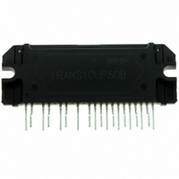
IRAMS10UP60B
Description
PLUG N DRIVE INTELLIGENT PWR MOD
Manufacturer
International Rectifier
Series
iMOTION™r
Type
IGBTr
Specifications of IRAMS10UP60B
Configuration
3 Phase
Current
10A
Voltage
600V
Voltage - Isolation
2000Vrms
Package / Case
PCB Module
Current, Input Bias
200 μA
Current, Quiescent Supply
165 μA
Current, Rms Phase
10 A
Frequency
20 KHz
Number Of Pins
25
Power Dissipation
2.2 W
Switching Loss
275 μJ
Temperature, Junction, Maximum
150 °C
Voltage, Breakdown, Collector To Emitter
600 V
Voltage, Input
20 + 0.3 V
Voltage, Input, High Level
3 V
Voltage, Input, Low Level
0.8 V
Voltage, Supply
20 V
Lead Free Status / RoHS Status
Lead free / RoHS Compliant
Other names
*IRAMS10UP60B
Available stocks
Company
Part Number
Manufacturer
Quantity
Price

Part Number:
IRAMS10UP60B
Manufacturer:
IR
Quantity:
20 000
Company:
Part Number:
IRAMS10UP60B-2
Manufacturer:
ST
Quantity:
1 001
Company:
Part Number:
IRAMS10UP60B-2
Manufacturer:
IR
Quantity:
5 510
Part Number:
IRAMS10UP60B-S
Manufacturer:
IR
Quantity:
20 000


Driver only timing unless otherwise specified.)
T
T
T
T
D
M
T
T
V
applicable to all six channels. (Note 3)
V
V
V
V
V
V
I
I
I
I
I
I
I
V(I
V(I
R
Symbol
Symbol
Dynamic Electrical Characteristics
www.irf.com
Static Electrical Characteristics Driver Function
QBS
QCC
LK
IN+,
IN-,
TRIP+
TRIP-
ON
OFF
FLIN
BLT-Trip
ITrip
FLT-CLR
BIAS
INH
INL
CCUV+,
CCUV-,
CCUVH,
IN,Clamp
ON
T
T
TRIP
TRIP
,
I
, V
FLT
, V
I
EN-
(V
EN+
)
, HYS)
V
ENL
ENH
V
V
CC
BSUV-
BSUVH
BSUV+
, V
BS1,2,3
Parameter
Input to Output propagation turn-
on delay time (see fig.11)
Input to Output propagation turn-
off delay time (see fig. 11)
Input Filter time (HIN, LIN)
I
Dead Time (V
Matching Propagation Delay Time
(On & Off)
I
propagation delay (see fig. 2)
Post I
clear time (see fig. 2)
)=15V, unless otherwise specified. The V
TRIP
Trip
Logic "0" input voltage
Logic "1" input voltage
V
V
V
Input Clamp Voltage (HIN, LIN, I
Quiescent V
Quiescent V
Offset Supply Leakage Current
Input bias current V
Input bias current V
I
I
I
I
Definition
Fault Output ON Resistance
TRIP
TRIP
TRIP
TRIP
CC
CC
CC
to six switch to turn-off
Blancking Time
and V
and V
and V
bias current V
bias current V
threshold Voltage
Input Hysteresis
Trip
to six switch to turn-off
BS
BS
BS
BS
CC
supply undervoltage Positive going threshold
supply undervoltage Negative going threshold
supply undervoltage lock-out hysteresis
BS
supply current V
supply current V
=V
DD
ITRIP
ITRIP
=15V)
IN
IN
=5V
=0V
=5V
=0V
IN
IN
=0V
=0V
TRIP
Min
100
100
220
) I
---
---
---
---
---
---
IN
=10µA
IN
and I
Typ
590
700
200
150
290
7.7
6.7
40
---
IN
parameters are referenced to COM/I
Max
1.75
360
---
---
---
75
---
---
Units Conditions
ms
ns
ns
ns
ns
ns
ns
µs
IRAMS10UP60B
10.6
10.4
Min
440
3.0
4.9
---
---
---
---
---
---
---
---
---
---
---
V
V
V
V
V
time> 400ns
V
T
T
CC
IN
IN
BS
CC
CC
C
C
= 25°C
= 100°C
=0 & V
=0 & V
=V
=V
= V
=V
CC
BS
BS
BS
= 15V, I
=15V
= 15V, I
= 15V, external dead
11.1
10.9
Typ
200
100
490
0.2
5.2
---
---
---
---
---
30
70
50
IN
IN
0
=5V
=5V
C
C
TRIP
=10A, V
=10A, V
Max
11.6
11.4
3.35
165
300
220
100
540
100
0.8
5.5
---
---
60
---
1
and are
+
+
=400V
=400V
Units
ohm
mA
mV
mV
µA
µA
µA
µA
µA
µA
V
V
V
V
V
V
5
Related parts for IRAMS10UP60B
Image
Part Number
Description
Manufacturer
Datasheet
Request
R

Part Number:
Description:
SCHOTTKY RECTIFIER
Manufacturer:
International Rectifier Corp.
Datasheet:
Part Number:
Description:
SCHOTTKY RECTIFIER
Manufacturer:
International Rectifier Corp.
Datasheet:
Part Number:
Description:
SCHOTTKY RECTIFIER
Manufacturer:
International Rectifier Corp.
Datasheet:
Part Number:
Description:
SCHOTTKY RECTIFIER
Manufacturer:
International Rectifier Corp.
Datasheet:
Part Number:
Description:
SCHOTTKY RECTIFIER
Manufacturer:
International Rectifier Corp.
Datasheet:
Part Number:
Description:
SCHOTTKY RECTIFIER
Manufacturer:
International Rectifier Corp.
Datasheet:
Part Number:
Description:
SCHOTTKY RECTIFIER
Manufacturer:
International Rectifier Corp.
Datasheet:
Part Number:
Description:
SCHOTTKY RECTIFIER
Manufacturer:
International Rectifier Corp.
Datasheet:
Part Number:
Description:
SCHOTTKY RECTIFIER
Manufacturer:
International Rectifier Corp.
Datasheet:
Part Number:
Description:
SCHOTTKY RECTIFIER
Manufacturer:
International Rectifier Corp.
Datasheet:
Part Number:
Description:
SCHOTTKY RECTIFIER
Manufacturer:
International Rectifier Corp.
Datasheet:
Part Number:
Description:
SCHOTTKY RECTIFIER
Manufacturer:
International Rectifier Corp.
Datasheet:
Part Number:
Description:
SCHOTTKY RECTIFIER
Manufacturer:
International Rectifier Corp.
Datasheet:
Part Number:
Description:
SCHOTTKY RECTIFIER
Manufacturer:
International Rectifier Corp.
Datasheet:
Part Number:
Description:
SCHOTTKY RECTIFIER
Manufacturer:
International Rectifier Corp.
Datasheet: