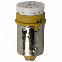
A22-24AY Omron, A22-24AY Datasheet - Page 25

A22-24AY
Manufacturer Part Number
A22-24AY
Description
LAMP A22 SERIES 24VAC/DC LED YLW
Manufacturer
Omron
Type
LED, 10.6 mm Diameterr
Series
A22r
Specifications of A22-24AY
Accessory Type
LED Lamp Replacement
Color
Yellow
Illumination
Illuminated
Contact Rating
8 mAmps at 24 VoltsAC/DC
Height
20 mm
Illumination Color
Yellow
Mounting Style
Snap In
Termination Style
Socket
For Use With/related Products
A22 Series
For Use With
Z1496 - SWITCH PB RND MOM SPST-NO ILLZ1495 - SWITCH PB ILL RND MOM SPST-NOZ1492 - SWITCH PB RND MOM SPST-NC ILLZ1494 - SWITCH PB ILL RND MOM SPST-NOZ1486 - SWITCH PB ILL RND MOM SPST-NOZ1485 - SWITCH PB ILL RND MOM SPST-NOZ1482 - SWITCH PB RND MOM SPST-NC ILLZ1484 - SWITCH PB ILL RND MOM SPST-NOZ1483 - SWITCH PB RND MOM SPST-NO ILLZ1477 - SWITCH PB SQ MOM SPST-NO ILL-YLWZ1476 - SWITCH PB SQ MOM SPST-NO ILL-WHTZ1475 - SWITCH PB SQ MOM SPST-NO ILL-GRNZ1474 - SWITCH PB SQ MOM SPST-NO ILL-BLU
Lead Free Status / RoHS Status
Lead free / RoHS Compliant
Lead Free Status / RoHS Status
Lead free / RoHS Compliant, Lead free / RoHS Compliant
Other names
A2224AY
Z1578
Z1578
- Current page: 25 of 265
- Download datasheet (11Mb)
A3D
Specifications
Contact Rating: 30 VDC, 0.1 A (Minimum Appli-
cable Load: 5 VDC, 1 mA)
The above ratings conform to JIS C4505, for testing under the fol-
lowing conditions.
Built-in LED Lamp
Note: 1. The above ratings are for an ambient temperature of 25°C.
Note: 1. With alternate operation models, 60 operations/minute max. One operation cycle consists of set and reset operations.
Forward voltage, V
Forward current, I
Permissible dissipation, PD
Reverse voltage, V
Operating frequency
Insulation resistance
Dielectric strength
Vibration resistance
Shock resistance
Life expectancy
Weight
Ambient operating temperature
Ambient operating humidity
Ambient storage temperature
Degree of protection
Electric shock protection class
PTI (proof tracking index)
Pollution degree
Ratings
Characteristics
2. The built-in LED lamp has no limiting resistor and so it is necessary to connect an external resistor within the range shown in the
3. Refer to the characteristic graphs of V
4. The same LED lamp is used for both yellow illumination and white illumination and so the ratings are the same.
2. The figure for dielectric strength between lamp terminals is for when the LED lamp is not mounted.
3. “Malfunction” in the above table indicates malfunctions of less than 1 ms.
above table. (For details of calculation formulas, refer to page 28.)
g ,
,
g
F
F
F
F
R
Item
Reference value (See note 3.)
Maximum value
Reference value
Absolute maximum value
Absolute maximum value
Absolute maximum value
Mechanical: 120 operations/minute max. (See note 1.)
Electrical: 20 operations/minute max.
100 MΩ min. (at 500 VDC)
1,000 VAC, 50/60 Hz for 1 minute between terminals of same polarity
2,000 VAC, 50/60 Hz for 1 minute between terminals of different polarity, and between each
terminal and ground
1,000 VAC, 50/60 Hz for 1 minute between lamp terminals (See note 2.)
Malfunction: 10 to 55 Hz, 1.5 mm double amplitude (See note 3.)
Destruction: 500 m/s
Malfunction: 150 m/s
Mechanical:
Momentary operation models: 1,000,000 operations min.
Alternate operation models: 100,000 operations min.
(One operation consists of set and reset operations.)
Electrical: 100,000 operations min.
Approx. 3 g
–10_C to 55_C (with no icing or condensation)
35% to 85%
–25_C to 65_C
IP40
Class II
175
3 (IEC947-5-1)
F
– I
F
on page 24.
2
2
(See note 3.)
1.7 V
2.0 V
20 mA
50 mA
100 mW
4 V
1. Load: Resistive load
2. Mounting conditions: No vibration or shock
3. Ambient temperature: 20 $2_C.
4. Operating frequency: 20 times/min.
Red
2.2 V
2.5 V
20 mA
50 mA
125 mW
4 V
Yellow (White)
(See note 4.)
Color
2.1 V
2.5 V
20 mA
50 mA
122 mW
4 V
Green
A3D
23
Related parts for A22-24AY
Image
Part Number
Description
Manufacturer
Datasheet
Request
R

Part Number:
Description:
SWITCH PB ILLUM RND MOM SPST BLU
Manufacturer:
Omron
Datasheet:

Part Number:
Description:
SWITCH PB ILLUM RND MOM SPST BLU
Manufacturer:
Omron
Datasheet:

Part Number:
Description:
SWITCH PB ILLUM RND MOM SPST GRN
Manufacturer:
Omron
Datasheet:

Part Number:
Description:
SWITCH PB ILLUM RND MOM SPST GRN
Manufacturer:
Omron
Datasheet:

Part Number:
Description:
SWITCH PB ILLUM RND MOM SPST RED
Manufacturer:
Omron
Datasheet:

Part Number:
Description:
SWITCH PB ILLUM RND MOM SPST RED
Manufacturer:
Omron
Datasheet:

Part Number:
Description:
SWITCH PB ILLUM RND MOM SPST WHT
Manufacturer:
Omron
Datasheet:

Part Number:
Description:
SWITCH PB ILLUM RND MOM SPST WHT
Manufacturer:
Omron
Datasheet:

Part Number:
Description:
SWITCH PB ILLUM RND MOM SPST YEL
Manufacturer:
Omron
Datasheet:

Part Number:
Description:
SWITCH PB ILLUM RND MOM SPST YEL
Manufacturer:
Omron
Datasheet:

Part Number:
Description:
SWITCH PB ILLUM RND MOM DPST BLU
Manufacturer:
Omron
Datasheet:

Part Number:
Description:
SWITCH PB ILLUM RND MOM SPST BLU
Manufacturer:
Omron
Datasheet:

Part Number:
Description:
SWITCH PB ILLUM RND MOM DPST BLU
Manufacturer:
Omron
Datasheet:

Part Number:
Description:
SWITCH PB ILLUM RND MOM DPST GRN
Manufacturer:
Omron
Datasheet:

Part Number:
Description:
SWITCH PB ILLUM RND MOM SPST GRN
Manufacturer:
Omron
Datasheet:


