D2F-01 Omron, D2F-01 Datasheet
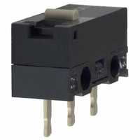
BUTTON SWITCH PCB SPDT .1A 150GF

D2F-01

Manufacturer Part Number
D2F-01
Description
BUTTON SWITCH PCB SPDT .1A 150GF
Manufacturer
Omron
Series
D2Fr
Type
Snap Actionr
Datasheets

Specifications of D2F-01

Circuit
SPDT
Switch Function
On-Mom
Contact Rating @ Voltage
0.1A @ 30VDC
Actuator Type
Round (Pin Plunger)
Mounting Type
Through Hole
Termination Style
PC Pin
Operating Force
150gf
Contact Form
SPDT
Contact Rating
0.1 Amp
Actuator
Plunger, Pin
Microswitch Type
Ultra Subminiature
Actuator Style
Pin Plunger
Operating Force Max
150gf
Contact Voltage Ac Nom
125V
Contact Voltage Dc Nom
30V
Contact Current Max
100mA
Body Style
Ultra Subminiature
Brand/series
D2F-01 Series
Current, Rating
0.1 A
Dielectric Strength
1500 VAC
Force, Operating
150 g
Mounting Hole Size
1.2 mm
Number Of Poles
1
Operation
Snap Action
Standards
UL Listed, CSA Certified, RoHS Compliant
Temperature Rating
-25 to +65 °C
Termination
Through Hole
Voltage, Rating
30 VDC
Lead Free Status / RoHS Status
Lead free / RoHS Compliant
Lead Free Status / RoHS Status
Lead free / RoHS Compliant, Lead free / RoHS Compliant
Other names
D2F01
SW501

Available stocks

Company
Part Number
Manufacturer
Quantity
Price
Part Number:
D2F-01
Manufacturer:
OMRON
Quantity:
12 000
Part Number:
D2F-01-A1
Manufacturer:
OMRON
Quantity:
8 000
Part Number:
D2F-01F
Manufacturer:
OMRON
Quantity:
365
Part Number:
D2F-01FL3
Manufacturer:
OMRON
Quantity:
5 000
Part Number:
D2F-01FL3-A
Manufacturer:
OMRON
Quantity:
8 000
Part Number:
D2F-01L
Manufacturer:
OMRON
Quantity:
12 000
Part Number:
D2F-01L
Manufacturer:
OMRON
Quantity:
472
Company:
Part Number:
D2F-01L-AQ
Quantity:
6 600
Company:
Part Number:
D2F-01L3
Quantity:
4 689
Subminiature Size Ideal for PCB
Mounting (12.8×6.5×5.8 (W×H×D))
Ordering Information
1. Ratings
2. Maximum Operating Force
3. Actuator
D2F-@@@@
RoHS Compliant
Incorporating a snapping mechanism made with
two highly precise split springs that ensures a
long durability.
Using Insertion molded terminals and a two-stage
bottom with different levels prevent flux penetra-
tion.
Self-clinching PCB, right-angled, left-angled, and
solder terminals are available.
Meets a wide range of applications, including
home
machines, and communications equipment.
Model Number Legend
None: General loads
01:
None: 1.47 N {150 gf}
F:
Note:These values are for the pin plunger models.
None: Pin plunger
L:
L2:
L3:
L30:
Ultra Subminiature Basic Switch
1
Micro loads (0.1 A at 30 VDC)
0.74 N {75 gf}
Hinge lever
Hinge roller lever
Simulated roller lever (R1.3)
Simulated roller lever (R2.5)
2 3
appliances,
4
audio
equipment,
office
4. Terminals
None: PCB terminals/straight terminals
-T:
-A:
-A1:
-D3:
-D:
Self-clinching PCB terminals
Right-angled PCB terminals
Left-angled PCB terminals
Solder terminals
Compact solder terminals
D2F
1

Related parts for D2F-01

D2F-01 Summary of contents

Page 1

... None: Pin plunger L: Hinge lever L2: Hinge roller lever L3: Simulated roller lever (R1.3) L30: Simulated roller lever (R2.5) equipment, office 4. Terminals None: PCB terminals/straight terminals -T: -A: -A1: -D3: -D: D2F Self-clinching PCB terminals Right-angled PCB terminals Left-angled PCB terminals Solder terminals Compact solder terminals 1 ...

Page 2

... D2F-01FL2-A D2F-01L2-A1 D2F-01FL2-A1 D2F-01L2-D3 D2F-01FL2-D3 D2F-01L2-D D2F-01FL2-D D2F-01L3 D2F-01FL3 D2F-01L3-T D2F-01FL3-T D2F-01L3-A D2F-01FL3-A D2F-01L3-A1 D2F-01FL3-A1 D2F-01L3-D3 D2F-01FL3-D3 D2F-01L3-D D2F-01FL3-D D2F-01L30 D2F-01FL30 D2F-01L30-T D2F-01FL30-T D2F-01L30-A D2F-01FL30-A D2F-01L30-A1 D2F-01FL30-A1 D2F-01L30-D3 D2F-01FL30-D3 D2F-01L30-D D2F-01FL30-D D2F-01 models General-purpose Low operating 1.47N {150gf} 0.74N {75gf} --- 0.1 A ...

Page 3

... D2F models: (initial value) D2F-F models: 50 mΩ max. D2F-01 models: 100 mΩ max. Dielectric strength (see note 2) 600 VAC, 50/60 Hz for 1 min between terminals of the same polarity 1,500 VAC, 50/60 Hz for 1 min between current-carrying metal parts and ground, and between each ...

Page 4

... Unless otherwise specified, a tolerance of ±0.4 mm applies to all dimensions. 3. The following illustrations and drawings are for D2F models with PCB terminals. Self-clinching, solder, and right-angled, left- angled terminals are omitted from the following drawings. Refer to page 4 for these terminals. When ordering, replace @ with the code for the terminal that you need ...

Page 5

... D2F-01F@ OF max. 1.47 N {150 gf} 0.74 N {75 gf} RF min. 0.20 N {20 gf} 0. gf} PT max. 0 min. 0. max. 0. 5.5±0.3 mm Model D2F-L@ D2F-FL@ D2F-01L@ D2F-01FL@ OF max. 0.78 N {80 gf} 0.25 N {25 gf} RF min. 0. gf} 0. gf} OT min. 0. max. 0 max 6.8±1.5 mm Model D2F-L2@ D2F-FL2@ D2F-01L2@ D2F-01FL2@ OF max ...

Page 6

... Inoperable range D2F Model D2F-L30@ D2F-FL30@ D2F-01L30@ D2F-01FL30@ OF max. 0.54 N {55 gf} 0.3 N {31 gf} RF min. 0. gf} 0. gf} OT min. 0 max. 0 max. 12 9.5±1.0 mm –6 /operations Operating range for Operating range general-load for micro load models models D2F-01 D2F Current (mA) ...

Related keywords