D2F-01 Omron, D2F-01 Datasheet
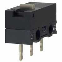
D2F-01
Specifications of D2F-01
SW501
Available stocks


Related parts for D2F-01


D2F-01 Summary of contents
Page 1
... D2F-01-A 30VDC plunger 0.1A @ Pin D2F-01- A1 30VDC plunger 0.1A @ Pin D2F-01-D 30VDC plunger 0.1A @ Pin D2F-01-T 30VDC plunger 0.1A @ Pin D2F-01F 30VDC plunger D2F-01F- 0.1A @ Pin 30VDC plunger A 0.1A @ Pin D2F-01F- A1 30VDC plunger Contact Operating Seal type Termination form Force SPDT ...
Page 2
... Soldered Right-angle Left-angle D2F-01F-D D2F-01F-A D2F-01F-A1 D2F-01-D D2F-01-A D2F-01-A1 D2F-F-D D2F-F-A D2F-F-A1 D2F-D D2F-A D2F-A1 D2F-01FL-D D2F-01FL-A D2F-01FL-A1 D2F-01L-D D2F-01L-A D2F-01L-A1 D2F-FL-D D2F-FL-A D2F-FL-A1 D2F-L-D D2F-L-A D2F-L-A1 D2F-01FL3-D D2F-01FL3-A D2F-01FL3-A1 D2F-01L3-D D2F-01L3-A D2F-01L3-A1 D2F-FL3-D D2F-FL3-A D2F-FL3-A1 D2F-L3-D D2F-L3-A D2F-L3-A1 D2F-01FL2-D D2F-01FL2-A ...
Page 3
... Malfunction durability Ambient temperature Operating Humidity Operating Service life Mechanical Electrical Weight Note: Data shown are of initial value. ■ Operating Characteristics Characteristics Part number D2F-01F-@, D2F-F-@ D2F-01-@, D2F-@ OF max 150 g RF min max. 0.5 mm (0.020 in) 0.5 mm (0.020 in) OT min. 0.25 mm (0.009 in) ...
Page 4
... Contact Form ■ Approvals UL (File No. E41515), CSA (File No. LR21642), EN conforms 61058-1 Type Rating D2F Series, D2F-01 Series 3 A, 125 VAC 1 A, 125 VAC VDC 0 VDC 0 VDC Note: The rated values approved by each of the safety standards (e.g.UL,CSA) may be different from the performance characteristics individually defined in this catalog ...
Page 5
... D2F-@ D2F-F-@ ■ Hinge Lever D2F-01L-@ D2F-01FL-@ D2F-L-@ D2F-FL-@ ■ Simulated Roller Lever D2F-01L3-@ D2F-01FL3-@ D2F-L3-@ D2F-FL3-@ ■ Roller Lever D2F-01L2-@ D2F-01FL2-@ D2F-L2-@ D2F-FL2-@ Note: 1. Unless otherwise specified, a tolerance of ± 0.4 mm applies to all dimensions. 2. Omitted dimensions are the same as pin plunger type. ...
Page 6
... Terminals D2F type PCB terminal D2F-D type Soldered terminal D2F-A type Right-angle terminal D2F-T type Self-supporting terminal D2F-A1 type Left-angle terminal Snap Action Switch D2F 5 ...
Page 7
... Precautions ■ Mounting Mount the D2F switch onto the PC board as shown in the following diagram, using 2-pitch (2 x 2.54 mm) terminal spacing. ■ PC Board Machining ■ Dimensions The use of molded components is recommended for mounting pur- poses. ■ Molded Pin Mounting Diagram When screw mounting, use M2 screws together with washers. Fas- ten the screws applying 0 ...