SS-3GPD Omron, SS-3GPD Datasheet - Page 5
SS-3GPD
Manufacturer Part Number
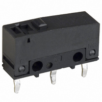
SS-3GPD
Description
SWITCH BASIC SPDT 3A PCB
Manufacturer
Omron
Series
SSr
Type
Basic Switchesr
Specifications of SS-3GPD
Circuit
SPDT
Switch Function
On-Mom
Contact Rating @ Voltage
3A @ 125VAC
Actuator Type
Round (Pin Plunger)
Mounting Type
Through Hole
Termination Style
PC Pin
Operating Force
150gf
Microswitch Type
Miniature
Actuator Style
Pin Plunger
Operating Force Max
153gf
Contact Voltage Ac Nom
125V
Contact Voltage Dc Nom
30V
Contact Current Max
3A
Actuator
Plunger, Pin
Contact Form
SPDT
Contact Rating
3 Amps at 125 Volts
Post Position
Straight Vertical
Lead Free Status / RoHS Status
Lead free / RoHS Compliant
Lead Free Status / RoHS Status
Lead free / RoHS Compliant, Lead free / RoHS Compliant
Other names
SS3GPD
SW769
SW769
Available stocks
Company
Part Number
Manufacturer
Quantity
Price


SS-P
Precautions
Refer to General Information.
■
Connecting to Solder Terminals
When soldering the lead wire to the terminal, first insert the lead
wire conductor through the terminal hole and then conduct sol-
dering.
Make sure that the temperature at the tip of the soldering iron is
350 to 400°C. Do not take more than 3 seconds to solder the
switch terminal, and do not impose external force on the terminal
for 1 min after soldering. Improper soldering involving an exces-
sively high temperature or excessive soldering time may deterio-
rate the characteristics of the Switch.
Connecting to Quick-connect Terminals
Wire the quick-connect terminals (#110) with receptacles. Insert
the terminals straight into the receptacles. Do not impose exces-
sive force on the terminal in the horizontal direction, otherwise the
terminal may be deformed or the housing may be damaged.
Connecting to PCB Terminal Boards
When using automatic soldering baths, we recommend soldering
at 260±5°C within 5 seconds. Make sure that the liquid surface of
the solder does not flow over the edge of the board.
When soldering by hand, as a guideline, solder with a soldering
iron with a tip temperature of 350 to 400°C within 3 seconds, and
do not apply any external force for at least 1 minutes after solder-
ing. When applying solder, keep the solder away from the case of
the Switch and do not allow solder or flux to enter the case.
■
Mounting
Turn OFF the power supply before mounting or removing the
Switch, wiring, or performing maintenance or inspection. Failure
to do so may result in electric shock or burning.
Use M2.3 mounting screws with plane washers or spring washers
to securely mount the Switch. Tighten the screws to a torque of
0.23 to 0.26 N·m {2.3 to 2.7 kgf·cm}.
Mount the Switch onto a flat surface. Mounting on an uneven sur-
face may cause deformation of the Switch, resulting in faulty oper-
ation or breakage in the housing.
Operating Stroke Setting
Take particular care in setting the operating stroke for the pin
plunger models. Make sure that the operating stroke is 60% to
90% of the rated OT distance. Do not operate the actuator
exceeding the OT distance, otherwise the durability of the Switch
may be shortened.
Cautions
Correct Use
Using Micro Loads
Using a model for ordinary loads to open or close the contact of a
micro load circuit may result in faulty contact. Use models that
operate in the following range. However, even when using micro
load models within the operating range shown below, if inrush
current occurs when the contact is opened or closed, it may
increase contact wear and so decrease durability. Therefore,
insert a contact protection circuit where necessary.
The minimum applicable load is the N-level reference value. This
value indicates the malfunction reference level for the reliability
level of 60% (
cates that the estimated malfunction rate is less than 1/2,000,000
operations with a reliability level of 60%.
30
24
12
5
0
0.1
0.16 mA
Inoperable
range
1 mA
λ
1
60). The equation,
Operating range
for micro load
models SS-01P
10
26 mA
100 mA 160 mA
100 mA
100
λ
60 = 0.5 × 10
Operating
range for
general-
load models
SS-3P
Current (mA)
1,000
−6
/operations indi-
SS-P
5
Related parts for SS-3GPD
Image
Part Number
Description
Manufacturer
Datasheet
Request
R

Part Number:
Description:
Basic / Snap Action / Limit Switches PIN PLUNGER TAB TERM
Manufacturer:
Omron
Datasheet:

Part Number:
Description:
SWITCH BASIC SPDT 3A SLDR
Manufacturer:
Omron
Datasheet:

Part Number:
Description:
SWITCH BASIC SPDT 3A .110QC
Manufacturer:
Omron
Datasheet:

Part Number:
Description:
SWITCH BASIC SPDT 3A PCB
Manufacturer:
Omron
Datasheet:

Part Number:
Description:
SWITCH LEVER SPDT 3A SLDR
Manufacturer:
Omron
Datasheet:

Part Number:
Description:
SWITCH LEVER SPDT 3A .110QC
Manufacturer:
Omron
Datasheet:

Part Number:
Description:
SWITCH SIM ROLLER SPDT 3A PCB
Manufacturer:
Omron
Datasheet:

Part Number:
Description:
SWITCH ROLLER LEVER 3A SLDR
Manufacturer:
Omron
Datasheet:
Part Number:
Description:
SWITCH SIM ROLLER SPDT 3A PCB
Manufacturer:
Omron
Datasheet:

Part Number:
Description:
SWITCH LEVER SPDT 3A PCB
Manufacturer:
Omron
Datasheet:

Part Number:
Description:
SWITCH SIM ROLLER SPDT 3A .110QC
Manufacturer:
Omron
Datasheet:
Part Number:
Description:
SWITCH LEVER SPDT 3A PCB
Manufacturer:
Omron
Datasheet:

Part Number:
Description:
Subminiature Basic Switch
Manufacturer:
Omron
Datasheet: