D2SW-P2L3H Omron, D2SW-P2L3H Datasheet - Page 6
D2SW-P2L3H
Manufacturer Part Number
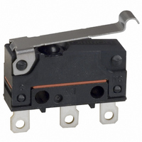
D2SW-P2L3H
Description
SWITCH SIM ROLLER SPDT 2A SLDR
Manufacturer
Omron
Series
D2SW-Pr
Type
Basic/Snap Actionr
Specifications of D2SW-P2L3H
Circuit
SPDT
Switch Function
On-Mom
Contact Rating @ Voltage
2A @ 250VAC
Actuator Type
Lever, Simulated Roller
Mounting Type
Chassis Mount
Termination Style
Solder Lug
Operating Force
61gf
Contact Form
SPDT
Contact Rating
2 Amps at 50 Volts
Actuator
Simulated Roller Lever
Ingress Protection
IP67, Watertight
Microswitch Type
Subminiature
Actuator Style
Simulated Roller Lever
Operating Force Max
0.6N
Contact Voltage Ac Nom
250V
Contact Voltage Dc Nom
30V
Contact Current Max
2A
Body Style
Subminiature
Current, Rating
2 A
Dielectric Strength
1500 VAC
Force, Operating
1.8 N (Max.)
Ip Rating
IP67
Mounting Hole Size
M2.3
Number Of Poles
1
Operation
Snap Action
Standards
UL Recognized
Temperature Rating
-20 to +70 °C
Termination
Solder
Voltage, Rating
250 VAC
Mounting
PCB
Lead Free Status / RoHS Status
Lead free / RoHS Compliant
Lead Free Status / RoHS Status
Lead free / RoHS Compliant, Lead free / RoHS Compliant
Other names
D2SWP2L3H
SW811
Z2129
Z2129
SW811
Z2129
Z2129


D2SW-P
Precautions
Refer to General Information.
■
Degree of Protection
Do not use this product in water. Although this models satisfy the
test conditions for the standard given below, this test is to check
the ingress of water into the switch enclosure after submerging
the Switch in water for a given time. Satisfying this test condition
does not mean that the Switch can be used in water.
IEC 60529: 2001 Degrees of protection provided by enclosures
(IP Code)
Code: IP67 (The test to meet the standard checks for water intru-
sion after immersion for 30 minutes.)
Do not operate the Switch when it is exposed to water spray, or
when water drops adhere to the Switch surface, or during sudden
temperature changes, otherwise water may intrude into the inte-
rior of the Switch due to a suction effect.
Prevent the Switch from coming into contact with oil and chemi-
cals. Otherwise, damage to or deterioration of Switch materials
may result.
Do not use the Switch in areas where it is exposed to silicon
adhesives, oil, or grease, otherwise faulty contact may result due
to the generation of silicon oxide.
The environment-resistant performance of the switch differs
depending on operating loads, ambient atmospheres, and instal-
lation conditions, etc. Please perform an operating test of the
switch in advance under actual usage conditions.
Connecting to Terminals
Connecting to Solder Terminals
When soldering the lead wire to the terminal, first insert the lead
wire conductor through the terminal hole and the conduct solder-
ing.
Make sure that the temperature at the tip of the soldering iron is
350 to 400°C. Do not take more than 3 seconds to solder the
switch terminal, and do not impose external force on the terminal
for 1 min after soldering. Improper soldering involving an exces-
sively high temperature or excessive soldering time may deterio-
rate the characteristics of the Switch.
Connecting to Quick-connect Terminals
Wire the quick-connect terminals (#110) with receptacles. Insert
the terminals straight into the receptacles. Do not impose exces-
sive force on the terminal in the horizontal direction, otherwise the
terminal may be deformed or the housing may be damaged.
Connecting to PCB Terminal Boards
When using automatic soldering baths, we recommend soldering
at 260±5°C within 5 seconds. Make sure that the liquid surface of
the solder does not flow over the edge of the board.
When soldering by hand, as a guideline, solder with a soldering
iron with a tip temperature of 350 to 400°C within 3 seconds, and
do not apply any external force for at least 1 minutes after solder-
ing. When applying solder, keep the solder away from the case of
the Switch and do not allow solder or flux to enter the case.
Side-actuated (Cam/Dog) Operation
When using a cam or dog to operate the Switch, factors such as
the operating speed, operating frequency, push-button indenta-
tion, and material and shape of the cam or dog will affect the
durability of the Switch. Confirm performance specifications under
actual operation conditions before using the Switch in applica-
tions.
6
Cautions
■
Mounting
Turn OFF the power supply before mounting or removing the
Switch, wiring, or performing maintenance or inspection. Failure
to do so may result in electric shock or burning.
Use M2.3 mounting screws with plane washers or spring washers
to securely mount the Switch. Tighten the screws to a torque of
0.23 to 0.26 N·m {2.3 to 2.7 kgf·cm}. Exceeding the specified
torgue may result in deterioration of the sealing or damage.
Mount the Switch onto a flat surface. Mounting on an uneven sur-
face may cause deformation of the Switch, resulting in faulty oper-
ation or damage.
Operating Body
Use an operating body with low frictional resistance and of a
shape that will not interfere with the sealing rubber, otherwise the
plunger may be damaged or the sealing may deteriorate.
With the pin plunger models, set the Switch so that the plunger
can be pushed in from directly above. Since the plunger is cov-
ered with a rubber cap, applying a force from lateral directions
may cause damage to the plunger or reduction in the sealing
capability.
Handling
Do not handle the Switch in a way that may cause damage to the
sealing rubber.
When handling the Switch, ensure that uneven pressure or, as
shown in the following diagram, pressure in a direction other than
the operating direction is not applied to the Actuator, otherwise
the Actuator or Switch may be damaged, or durability may be
decreased.
Wiring Molded Lead Wire Models
When wiring molded lead wire models, ensure that there is no
weight on the wire or that there are no sharp bends near the parts
where the wire is drawn out. Otherwise, damage to the Switch or
deterioration in the sealing may result.
Operating Stroke Setting
Set the operating stroke so that the actuator is completely disen-
gaged when the switch is in the free position (FP), and is pushed
to a point between 60% and 90% of the OT distance after the
switch is operated.
Insufficient or excessive pushing of the actuator may result in
decreased switch durability or damage to the switch.
Using Micro Loads
Using a model for ordinary loads to open or close the contact of a
micro load circuit may result in a faulty contact. Use models that
operate in the following range. However, even when using micro
load models within the operating range shown below, if inrush
current occurs when the contact is opened or closed, it may
increase contact wear and so decrease durability. Therefore,
insert a contact protection circuit where necessary. The minimum
applicable load is the N-level reference value. This value indicates
the malfunction reference level for the reliability level of 60%
(λ60).
Correct Use
Incorrect
Correct
Incorrect
D2SW-P
Related parts for D2SW-P2L3H
Image
Part Number
Description
Manufacturer
Datasheet
Request
R

Part Number:
Description:
Sealed Subminiature Basic Switch
Manufacturer:
Omron Corporation
Datasheet:

Part Number:
Description:
SWITCH BASIC SPDT 2A .110QC
Manufacturer:
Omron
Datasheet:

Part Number:
Description:
SWITCH SIM ROLL SPDT .1A .110QC
Manufacturer:
Omron
Datasheet:

Part Number:
Description:
SWITCH SIM ROLLER SPDT .1A PCB
Manufacturer:
Omron
Datasheet:

Part Number:
Description:
SWITCH BASIC SPDT .1A PCB
Manufacturer:
Omron
Datasheet:

Part Number:
Description:
SWITCH ROLLER LEVER SPDT 2A SLDR
Manufacturer:
Omron
Datasheet:
Part Number:
Description:
SWITCH SIM ROLLER SPDT .1A PCB
Manufacturer:
Omron
Datasheet:
Part Number:
Description:
SWITCH BASIC SPDT .1A .110QC
Manufacturer:
Omron
Datasheet:

Part Number:
Description:
SWITCH SIM ROLLER SPDT 2A WIRE
Manufacturer:
Omron
Datasheet:
Part Number:
Description:
SWITCH SIM ROLLER SPDT .1A WIRE
Manufacturer:
Omron
Datasheet:

Part Number:
Description:
Miniature Basic Switch
Manufacturer:
Omron
Datasheet:
Part Number:
Description:
SUBMINIATURE BASIC SWITCH
Manufacturer:
Omron
Datasheet:
Part Number:
Description:
Subminiature Basic Switch
Manufacturer:
Omron
Datasheet:
Part Number:
Description:
Subminiature Basic Switch
Manufacturer:
Omron
Datasheet:
Part Number:
Description:
Miniature Basic Switch
Manufacturer:
Omron
Datasheet: