D4BS-35FS Omron, D4BS-35FS Datasheet - Page 7
D4BS-35FS
Manufacturer Part Number
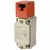
D4BS-35FS
Description
SWITCH SAFETY DOOR 10A SEALED
Manufacturer
Omron
Series
D4BSr
Type
Safety-Door Switchr
Datasheet
1.D4BS-K1.pdf
(10 pages)
Specifications of D4BS-35FS
Circuit
DPST (1-NO, 1-NC)
Switch Function
On-Off, Off-On
Contact Rating @ Voltage
10A @ 250VAC
Actuator Type
Panel Disconnect
Mounting Type
Chassis Mount
Termination Style
Screw Terminal
Operating Force
1960gf
Contact Form
DPDT
Contact Rating
10 Amps
Actuator
Plunger
Contact Configuration
DPST-1NO / 1NC
Contact Voltage Ac Max
600V
Contact Current Ac Max
10A
Switch Operation
ON
Switch Terminals
Screw
Contact Current Max
10A
Circuitry
DPST-1NO/1NC
Lead Free Status / RoHS Status
Lead free / RoHS Compliant
Lead Free Status / RoHS Status
na, Lead free / RoHS Compliant
Other names
D4BS35FS
Z2434
Z2434


Safety Precautions
Refer to the “Precautions for All Switches” on page I-2 and “Precautions for All Safety Door Switches” on page A-2.
■ Precautions for Safe Use
• Do not use the Switch submersed in oil or water or in locations
• Although the Switch body is protected from the ingress of dust or
• Always attach the cover after completing wiring and before using
■ Precautions for Correct Use
Tightening Torque
Loose screws may result in malfunction. Tighten the screws to the
specified torques.
Note: 1. Apply a torque of 0.78 to 0.88 N·m if the D4BS is a three-
Mounting Dimensions (M5)
M3.5 terminal screw (including ground
terminal screw)
Cover mounting screw (See note 1.)
Head mounting screw
M5 body mounting screw (See note 2.) 4.90 to 5.88 N·m
Operation Key mounting screw
Connector
Cap screw
continuously subject to splashes of oil or water. Doing so may result
in oil or water entering the Switch. (The IP67 degree of protection of
the Switch specifies the amount of water penetration after the
Switch is submerged in water for a certain period of time.)
water, avoid the ingress of foreign substance through the key hole
on the head.
Otherwise, accelerated wear or breaking may result.
the Switch. Electric shock may occur if the Switch is used without
the cover attached.
60
Standard Model
2. Apply a torque of 4.90 to 5.88 N·m for an Allen-head bolt.
conduit model.
For a pan head screw, apply a torque of 2.35 to 2.75 N·m.
30
Type
Mounting hole
Mounting side
Insertion hole for stud
5
0.15
0.05
dia. holes, max. height: 5
59.3 0.1
Three-conduit Model
5
0.05
0.15
0.59 to 0.78 N·m
1.18 to 1.37 N·m
0.78 to 0.98 N·m
2.35 to 2.75 N·m
1.77 to 2.16 N·m
1.27 to 1.67 N·m
Studs
dia. holes, max. height: 5
27 0.1
30
40
42
Torque
The D4BS can be mounted more securely by adding two studs, each
of which is 5 mm maximum in height and
5
Operation Key Mounting Dimensions
For safety, use screws that cannot be easily removed or a similar
means to prevent the Switch and Operation Key from being easily
removed.
Operation Key
Make sure that the Operation Key can be inserted properly with a tol-
erance of 0.5 mm in the upward, downward, left, or right direction,
otherwise the D4BS may soon become damaged.
Observe the specified insertion radius for the Operation Key and
insert it in a direction perpendicular to the key hole.
Changes in Head Mounting Direction
By removing the screws on the four corners of the head, the head
can be reset in any of four directions. The head direction can be
changed with or without the Operation Key inserted in the head.
Make sure that no foreign materials enter through the head and that
the head is tightened securely within the proper torque range.
0.05
0.15
mm in diameter as shown below.
Horizontal Mounting
Vertical Mounting
Adjustable Mounting (Horizontal)
Safety-door Switch
Incorrect
Incorrect
20
40
30
Greater
than 0.5
Greater
than 0.5
0.1
0.1
0.1
Two, M5
Two, M5
Two, M5
D4BS
A-33
Related parts for D4BS-35FS
Image
Part Number
Description
Manufacturer
Datasheet
Request
R

Part Number:
Description:
Interlock Safety Door Switch
Manufacturer:
Omron
Datasheet:
Part Number:
Description:
INTERLOCK SWITCH
Manufacturer:
Omron
Datasheet:
Part Number:
Description:
SAFETY DOOR SWITCH G1/2, 2NC
Manufacturer:
Omron
Datasheet:

Part Number:
Description:
Contact OSTI For Purchase
Manufacturer:
Omron
Datasheet:
Part Number:
Description:
Limit Switch
Manufacturer:
Omron
Datasheet:
Part Number:
Description:
Safety Door Switch
Manufacturer:
Omron
Datasheet:
Part Number:
Description:
Limit Switch
Manufacturer:
Omron
Datasheet:
Part Number:
Description:
SAFETY-DOOR SWITCH
Manufacturer:
Omron
Datasheet:
Part Number:
Description:
SAFETY-DOOR SWITCH
Manufacturer:
Omron
Datasheet:
Part Number:
Description:
LIMIT SWITCH ADJ ROLL LEVER
Manufacturer:
Omron
Datasheet: