D2FW-G283M Omron, D2FW-G283M Datasheet - Page 2
D2FW-G283M
Manufacturer Part Number
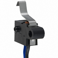
D2FW-G283M
Description
SWITCH LONGLEVER SPST-NO 1A SLD
Manufacturer
Omron
Series
D2FW-Gr
Type
Snap Actionr
Specifications of D2FW-G283M
Circuit
SPST-NO
Switch Function
Off-Mom
Contact Rating @ Voltage
1A @ 30VDC
Actuator Type
Lever, Leaf
Mounting Type
Chassis Mount
Termination Style
Wire Leads
Operating Force
300gf
Contact Form
SPST - NO
Contact Rating
1 Amp at 30 Volts
Actuator
Lever, Leaf
Microswitch Type
Subminiature
Actuator Style
Leaf Lever
Operating Force Max
300gf
Contact Voltage Dc Nom
30V
Contact Current Max
1A
Switch Terminals
Wire Leaded
Circuitry
SPST-NO
Body Style
Subminiature
Current, Rating
1 A
Dielectric Strength
1500 VAC
Ip Rating
IP67
Mounting Hole Size
4 mm
Number Of Poles
1
Operation
Snap Action
Termination
Lead Wire
Voltage, Rating
30 VDC
Mounting
Screw
Lead Free Status / RoHS Status
Lead free / RoHS Compliant
Lead Free Status / RoHS Status
Lead free / RoHS Compliant, Lead free / RoHS Compliant
Other names
D2FWG283M
SW514
SW514


D2FW-G
Specifications
■
Note:
■
Note:
■
Note:
2
Contact
Minimum applicable load
(see note)
Operating speed
Operating frequency
Insulation resistance
Contact resistance
Dielectric strength
Vibration resistance (see note 2)
Shock resistance (see note 2)
Durability (see note 3)
Degree of protection
Degree of protection against electric
shock
Proof tracking index (PTI)
Ambient operating temperature
Ambient operating humidity
Weight
30 VDC
Ratings
Characteristics
Contact Specifications
The ratings values apply under the following test conditions:
Ambient temperature: 20±2°C
Ambient humidity: 65±5%
Operating frequency: 30 operations/min
1. The data given above are initial values.
2. For the pin plunger models, the above values apply for use at the free position, operating position, and total travel position.
3. For testing conditions, consult your OMRON sales representative.
For more information on the minimum applicable load, refer to Using Micro Loads on page 4.
For the lever models, they apply at the total travel position.
The values shown apply for malfunctions of 1 ms max.
Specification
Material
Gap (standard value)
Rated voltage
Item
Item
1 mm to 500 mm/s
Mechanical: 120 operations/min max.
Electrical:
100 MΩ min. (at 500 VDC)
100 mΩ max.
600 VAC, 50/60 Hz for 1 min between terminals of the same polarity
1,500 VAC, 50/60 Hz for 1 min between current-carrying metal parts and ground, and between
each terminal and non-current-carrying metal parts
Malfunction: 10 to 55 Hz, 1.5-mm double amplitude
Destruction: 1,000 m/s
Malfunction: 300 m/s
Mechanical: 300,000 operations min. (60 operations/min)
Electrical: 30,000 operations min.
IEC IP67
Class I
175
–40°C to 85°C (at ambient humidity of 60% max.) (with no icing or condensation)
95% max. (for 5°C to 35°C)
Approx. 10.4 g (SPDT type)
Crossbar
Silver alloy
0.25 mm
100 mA at 5 VDC
1 A
D2FW-G2@ (general load models)
D2FW-G2@ (general load models)
(20 operations/min)
30 operations/min max.
D2FW-G2@
2
max.
2
max.
Resistive load
150 mΩ max.
Electrical: 100,000 operations min.
Gold alloy
1 mA at 5 VDC
0.1 A
D2FW-G0@ (micro load models)
D2FW-G0@ (micro load models)
(20 operations/min)
D2FW-G0@
D2FW-G
Related parts for D2FW-G283M
Image
Part Number
Description
Manufacturer
Datasheet
Request
R

Part Number:
Description:
SWITCH BASIC SPDT .1A SLD
Manufacturer:
Omron
Datasheet:

Part Number:
Description:
SWITCH BASIC SPDT 1A SLD
Manufacturer:
Omron
Datasheet:

Part Number:
Description:
SWITCH LEVER SPST-NO .1A SEALED
Manufacturer:
Omron
Datasheet:

Part Number:
Description:
SWITCH LEVER SPST-NO 1A SEALED
Manufacturer:
Omron
Datasheet:

Part Number:
Description:
SWITCH LONGLEVER SPST-NO .1A SLD
Manufacturer:
Omron
Datasheet:

Part Number:
Description:
SWITCH BASIC SPST-NC .1A SLD
Manufacturer:
Omron
Datasheet:
Part Number:
Description:
SWITCH BASIC SPST-NC 1A SLD
Manufacturer:
Omron
Datasheet:
Part Number:
Description:
SWITCH BASIC SPST-NC 1A SLD
Manufacturer:
Omron
Datasheet:
Part Number:
Description:
SWITCH BASIC SPST-NC .1A SLD
Manufacturer:
Omron
Datasheet:
Part Number:
Description:
SWITCH BASIC SPDT .1A SLD
Manufacturer:
Omron
Datasheet:
Part Number:
Description:
SWITCH BASIC SPDT 1A SLD
Manufacturer:
Omron
Datasheet:

Part Number:
Description:
G6S-2GLow Signal Relay
Manufacturer:
Omron Corporation
Datasheet:
Part Number:
Description:
Compact, Low-cost, SSR Switching 5 to 20 A
Manufacturer:
Omron Corporation
Datasheet: