D2FW-G283M Omron, D2FW-G283M Datasheet - Page 4
D2FW-G283M
Manufacturer Part Number
D2FW-G283M
Description
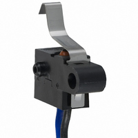
SWITCH LONGLEVER SPST-NO 1A SLD
Manufacturer
Omron
Series
D2FW-Gr
Type
Snap Actionr
Specifications of D2FW-G283M
Circuit
SPST-NO
Switch Function
Off-Mom
Contact Rating @ Voltage
1A @ 30VDC
Actuator Type
Lever, Leaf
Mounting Type
Chassis Mount
Termination Style
Wire Leads
Operating Force
300gf
Contact Form
SPST - NO
Contact Rating
1 Amp at 30 Volts
Actuator
Lever, Leaf
Microswitch Type
Subminiature
Actuator Style
Leaf Lever
Operating Force Max
300gf
Contact Voltage Dc Nom
30V
Contact Current Max
1A
Switch Terminals
Wire Leaded
Circuitry
SPST-NO
Body Style
Subminiature
Current, Rating
1 A
Dielectric Strength
1500 VAC
Ip Rating
IP67
Mounting Hole Size
4 mm
Number Of Poles
1
Operation
Snap Action
Termination
Lead Wire
Voltage, Rating
30 VDC
Mounting
Screw
Lead Free Status / RoHS Status
Lead free / RoHS Compliant
Lead Free Status / RoHS Status
Lead free / RoHS Compliant, Lead free / RoHS Compliant
Other names
D2FWG283M
SW514
SW514


D2FW-G
Long Leaf Lever Models
D2FW-G@8@M
Precautions
Refer to General Information.
■
Use the Switch within the specified electrical ratings. Using the
Switch outside of the rated values will not only shorten its service
life but may cause heat generation or fire damage. When turning
the power ON or OFF, use the rated voltage and current.
Degree of Protection
Do not use the Switch underwater. The Switch was tested and
found to meet the conditions necessary to meet the following
standard. The test checks for water intrusion after immersion for a
specified time period. The test does not check for switching oper-
ation underwater.
IEC Publication 529, degree of protection IP67.
Protection Against Chemicals
Prevent the Switch from coming into contact with oil or chemicals.
Otherwise, damage to or deterioration of Switch materials may
result.
■
Mounting
Turn OFF the power supply before mounting or removing the
Switch, wiring, or performing maintenance or inspection. Failure
to do so may result in electric shock or burning.
Use M4 mounting screws with plane washers or spring washers
to securely mount the Switch. Tighten the screws to a torque of
1.18 to1.47 N·m {12 to 15 kgf·cm}.
Mount the Switch onto a flat surface. Mounting on an uneven sur-
face may cause deformation of the Switch, resulting in faulty oper-
ation or breakage in the housing.
Switch Mounting
When mounting the Switch, do not apply force to the actuator in
any direction other than its operating direction.
4
Cat. No. B104-E1-02
Cautions
Correct Use
ALL DIMENSIONS SHOWN ARE IN MILLIMETERS.
To convert millimeters into inches, multiply by 0.03937. To convert grams into ounces, multiply by 0.03527.
COM AVS0.5 (Black)
t=0.2 stainless-steel lever
Molded lead wires
NO AVS0.5 (Blue)
NC AVS0.5 (Red)
4
4.2
+0.2
0
+0.2
0
3.5R
dia.
dia.
4.7
16±0.15
D2FW-G
23.5
(19)
15.3
4
A
0
−0.15
5
(5)
dia.
300±10
13.5
Operating
position
(OP)
Operation
Make sure that the switching object is perfectly separated from
the actuator when the switch is not operated and the actuator is
pressed appropriately by the switching object when the switch is
operated. The switching object must not move beyond its opera-
tional limit position, otherwise the Switch may be damaged.
Install the switching object so that its moving direction is the same
as that of the actuator.
Using Micro Loads
Using a model for ordinary loads to open or close the contact of a
micro load circuit may result in faulty contact. Use models that
operate in the following range. However, even when using micro
load models within the operating range shown below, if inrush
current occurs when the contact is opened or closed, it may
increase contact wear and so decrease durability. Therefore,
insert a contact protection circuit where necessary.
The minimum applicable load is the N-level reference value. This
value indicates the malfunction reference level for the reliability
level of 60% (λ 60). The equation, λ 60 = 0.5×10
indicates that the estimated malfunction rate is less than 1/
2,000,000 operations with a reliability level of 60%.
Free
position
(FP)
2
8
5
2
Operating
area of micro
load models
D2FW-G0@
OF
RF min.
OT min.
MD max.
FP max.
OP
TTP
2.94 N {300 gf}
0.59 N {60 gf}
1.0 mm
1.0 mm
19 mm
12±2 mm
8.5 mm
(reference value)
Current (mA)
Operating
area of
general-load
models
D2FW-G2@
–6
D2FW-G
/operations
Related parts for D2FW-G283M
Image
Part Number
Description
Manufacturer
Datasheet
Request
R

Part Number:
Description:
SWITCH BASIC SPDT .1A SLD
Manufacturer:
Omron
Datasheet:

Part Number:
Description:
SWITCH BASIC SPDT 1A SLD
Manufacturer:
Omron
Datasheet:

Part Number:
Description:
SWITCH LEVER SPST-NO .1A SEALED
Manufacturer:
Omron
Datasheet:

Part Number:
Description:
SWITCH LEVER SPST-NO 1A SEALED
Manufacturer:
Omron
Datasheet:

Part Number:
Description:
SWITCH LONGLEVER SPST-NO .1A SLD
Manufacturer:
Omron
Datasheet:

Part Number:
Description:
SWITCH BASIC SPST-NC .1A SLD
Manufacturer:
Omron
Datasheet:
Part Number:
Description:
SWITCH BASIC SPST-NC 1A SLD
Manufacturer:
Omron
Datasheet:
Part Number:
Description:
SWITCH BASIC SPST-NC 1A SLD
Manufacturer:
Omron
Datasheet:
Part Number:
Description:
SWITCH BASIC SPST-NC .1A SLD
Manufacturer:
Omron
Datasheet:
Part Number:
Description:
SWITCH BASIC SPDT .1A SLD
Manufacturer:
Omron
Datasheet:
Part Number:
Description:
SWITCH BASIC SPDT 1A SLD
Manufacturer:
Omron
Datasheet:

Part Number:
Description:
G6S-2GLow Signal Relay
Manufacturer:
Omron Corporation
Datasheet:
Part Number:
Description:
Compact, Low-cost, SSR Switching 5 to 20 A
Manufacturer:
Omron Corporation
Datasheet: