ASMT-YTB2-0BB02 Avago Technologies US Inc., ASMT-YTB2-0BB02 Datasheet

Standard LED - SMD RGB Full Color

ASMT-YTB2-0BB02

Manufacturer Part Number
ASMT-YTB2-0BB02
Description
Standard LED - SMD RGB Full Color
Manufacturer
Avago Technologies US Inc.
Datasheet

Specifications of ASMT-YTB2-0BB02

Led Size
3 mm x 2.8 mm
Illumination Color
Red, Green, Blue
Operating Voltage
2.1 V, 3.2 V, 3.2 V
Wavelength
622 nm, 530 nm, 470 nm
Luminous Intensity
745 mcd, 1600 mcd, 360 mcd
Mounting Style
SMD/SMT
Operating Current
20 mA
Lens Dimensions
2.3 mm x 2.3 mm
Lens Shape
Square
Maximum Operating Temperature
+ 110 C
Minimum Operating Temperature
- 40 C
Peak Wavelength
629 nm, 521nm, 464 nm
Package / Case
PLCC-6
Viewing Angle
120 deg
Lead Free Status / RoHS Status
Lead free / RoHS Compliant
Description
The high brightness black top surface tri-color PLCC-6
family of SMT LEDs has a separate heat path for each LED
dice, enabling the LED to be driven at higher current.
These SMT LEDs are in the high brightness category,
are high reliability devices, are high performance and
are designed for a wide range of environmental condi-
tions. By integrating the black top surface Avago devices
deliver better contrast enhancement for your applica-
tion. They also provide super wide viewing angle at 120°
with the built in reflector pushing up the intensity of the
light output. The high reliability characteristics and other
features make the black top surface tri-color PLCC-6 family
ideally suitable for exterior and interior full color signs ap-
plication conditions.
For easy pick & place, the LEDs are shipped in EIA-com-
pliant tape and reel. Every reel is shipped from a single
intensity and color bin; except red color providing better
uniformity. These tri-color LEDs are compatible with
reflow soldering process.
ASMT-YTB2-0BB02
High Brightness Tricolor PLCC6 Black Surface LED
Data Sheet
CAUTION: LEDs are Class 1C ESD sensitive. Please observe appropriate precautions during han-
dling and processing. Please refer to Avago Application Note AN-1142 for additional details.
Features
x Industry Standard PLCC-6 package (Plastic Leaded Chip
x High reliability LED package with silicone encapsulation
x High brightness using AlInGaP and InGaN dice
x Wide viewing angle at 120°
x Compatible with reflow soldering process
x JEDEC MSL 2a
x Water-Resistance (IPX6*) per IEC 60529:2001
*
Applications
x Indoor and outdoor full color display
Carrier) with individual addressable pin-out for higher
flexibility of driving configuration
technologies
The test is conducted on component level by mounting the
components on PCB with proper potting to protect the leads. It is
strongly recommended that customers perform necessary tests on
the components for their final application.

Related parts for ASMT-YTB2-0BB02

ASMT-YTB2-0BB02 Summary of contents

Page 1

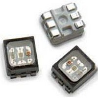
... ASMT-YTB2-0BB02 High Brightness Tricolor PLCC6 Black Surface LED Data Sheet Description The high brightness black top surface tri-color PLCC-6 family of SMT LEDs has a separate heat path for each LED dice, enabling the LED to be driven at higher current. These SMT LEDs are in the high brightness category, ...

Page 2

... Table 1. Device Selection Guide Color 1 - Min. Iv @20mA Part Number Bin ID (mcd) ASMT-YTB2-0BB02 U2 560 Notes: 1. The luminous intensity measured at the mechanical axis of the LED package and it is tested in pulsing condition. The actual peak of the spatial V radiation pattern may not be aligned with this axis. ...

Page 3

Table 2. Absolute Maximum Ratings (T A Parameter [1] DC forward current [2] Peak forward current Power dissipation Reverse voltage Maximum junction temperature T j max Operating temperature range Storage temperature range Notes: 1. Derate linearly as shown in Figure ...

Page 4

BLUE GREEN 0.6 0.4 0.2 0.0 400 450 500 550 WAVELENGTH - nm Figure 1. Relative Intensity vs Wavelength 5.0 4.5 4.0 3.5 Blue 3.0 2.5 2.0 1.5 1.0 0.5 0 FORWARD CURRENT-mA ...

Page 5

Red Green 0.0 -90 -60 -30 0 ANGULAR DISPLACEMENT-DEGREE Figure 5a. Radiation Pattern for X axis Figure 5c. Component Axis for Radiation Patterns 10 1 Red Green Blue 0.1 -40 -20 ...

Page 6

Figure 8a. Recommended soldering land pattern 1.7mm OD = 3.5mm Figure 9. Recommended Pick and Place Nozzle Tip 20 SEC. MAX. 240°C MAX. 3°C/SEC. MAX. 100-150°C 3°C/SEC. ...

Page 7

Figure 12. Carrier tape Dimension +0.5 2 –0 180 LABEL AREA (111 mm) WITH DEPRESSION (0.25 mm) Figure 13. Reel Dimension 7 Package Marking +0.10 1.50 2.00 ±0.05 –0 +0.10 1.00 ...

Page 8

USER FEED DIRECTION PRINTED LABEL Figure 14. Reeling Orientation Color Bin Selection ( Individual reel will contain parts from 1 half bin only Min Iv Bin (Minimum Intensity Bin) X Red Green ...

Page 9

Color Bin Limits Red Color Bin Table Bin ID Min Dom Full 618 Distribution Tolerance of each bin limit is ± Green Color Bin Table Bin ID Min Dom A 525.0 B 528.0 C 531.0 Tolerance of each ...

Page 10

Handling Precaution The encapsulation material of the LED is made of silicone for better product reliability. Since silicone is a soft material, avoid pressing on the silicon or poking the silicon with a sharp object as the product could be ...

Related keywords