TSL208R TAOS, TSL208R Datasheet - Page 8
TSL208R
Manufacturer Part Number
TSL208R
Description
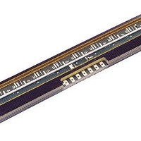
Photodiodes Linear Array 200 DPI
Manufacturer
TAOS
Type
Linear Sensor Arrayr
Datasheet
1.TSL208R.pdf
(10 pages)
Specifications of TSL208R
Peak Wavelength
1000 nm
Maximum Rise Time
500 ns
Maximum Fall Time
500 ns
Maximum Operating Temperature
+ 70 C
Minimum Operating Temperature
0 C
Product
Photodiode
Lead Free Status / RoHS Status
Lead free / RoHS Compliant


TSL208R
512 y 1 LINEAR SENSOR ARRAY
TAOS031E − MAY 2007
8
Copyright E 2007, TAOS Inc.
It is good practice on initial power up to run the clock (n+1) times after the first SI pulse to clock out indeterminate
data from power up. After that, the SI pulse is valid from the time following (n+1) clocks. The output will go into
a high-impedance state after the n+1 high clock edge. It is good practice to leave the clock in a low state when
inactive because the SI pulse required to start a new cycle is a low-to-high transition.
The integration time chosen is valid as long as it falls in the range between the minimum and maximum limits
for integration time. If the amount of light incident on the array during a given integration period produces a
saturated output (Max Voltage output), then the data is not accurate. If this occurs, the integration period should
be reduced until the analog output voltage for each pixel falls below the saturation level. The goal of reducing
the period of time the light sampling window is active is to lower the output voltage level to prevent saturation.
However, the integration time must still be greater than or equal to the minimum integration period.
If the light intensity produces an output below desired signal levels, the output voltage level can be increased
by increasing the integration period provided that the maximum integration time is not exceeded. The maximum
integration time is limited by the length of time the integrating capacitors on the pixels can hold their accumulated
charge. The maximum integration time should not exceed 100 ms for accurate measurements.
Although the linear array is capable of running over a wide range of operating frequencies up to a maximum
of 5 MHz, the speed of the A/D converter used in the application is likely to be the limiter for the maximum clock
frequency. The voltage output is available for the whole period of the clock, so the setup and hold times required
for the analog-to-digital conversion must be less than the clock period.
APPLICATION INFORMATION
r
www.taosinc.com
r
The LUMENOLOGY r Company
Related parts for TSL208R
Image
Part Number
Description
Manufacturer
Datasheet
Request
R

Part Number:
Description:
Microcontroller Modules & Accessories TAOS Eval Module w/USB Interface
Manufacturer:
TAOS
Part Number:
Description:
Optical Sensor Development Tools TAOS Eval Module
Manufacturer:
TAOS

Part Number:
Description:
Industrial Optical Sensors Ambient Light Sensor SMBus
Manufacturer:
TAOS
Datasheet:

Part Number:
Description:
Photodiodes TriColor Sensor RGB, Clear Ch
Manufacturer:
TAOS
Datasheet:

Part Number:
Description:
LED Displays Hexadecimal Display 4-bit
Manufacturer:
TAOS
Datasheet:

Part Number:
Description:
Photodiodes Linear Sensor Array 200dpi 64pix
Manufacturer:
TAOS
Datasheet:

Part Number:
Description:
Industrial Optical Sensors Ambient Light Sensor SMBus
Manufacturer:
TAOS
Datasheet:

Part Number:
Description:
Photodiodes Light to Voltage Converter
Manufacturer:
TAOS
Datasheet:

Part Number:
Description:
Photodiodes Linear Array 200 DPI
Manufacturer:
TAOS
Datasheet:

Part Number:
Description:
Photodiodes Light to Voltage Converter
Manufacturer:
TAOS
Datasheet:
Part Number:
Description:
Industrial Optical Sensors Ambient Light Sensor SMBus
Manufacturer:
TAOS
Datasheet:
Part Number:
Description:
Photodiodes TriColor Sensor RGB, Clear Ch
Manufacturer:
TAOS
Datasheet:
Part Number:
Description:
LED Displays Hexadecimal Display 4-bit
Manufacturer:
TAOS
Datasheet:
Part Number:
Description:
Photodiodes Linear Sensor Array 200dpi 64pix
Manufacturer:
TAOS
Datasheet:
