MM232R FTDI, MM232R Datasheet - Page 17
MM232R
Manufacturer Part Number
MM232R
Description
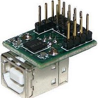
Interface Modules & Development Tools USB to Serial UART Mini Dev Mod FT232R
Manufacturer
FTDI
Type
Development Moduler
Specifications of MM232R
Interface Type
USB, Serial, UART
Data Bus Width
Serial
Operating Supply Voltage
1.8 V to 5.25 V
Product
Interface Modules
Supported Devices
FT232RQ
Svhc
No SVHC (18-Jun-2010)
Development Tool Type
Development Kit
Kit Features
Single Chip USB To Asynchronous Serial Data Transfer Interface, Entire USB Protocol Handled
Rohs Compliant
Yes
Supported Families
FT232RQ
Tool / Board Applications
USB To Serial UART Converter
For Use With/related Products
FT232R
Lead Free Status / RoHS Status
Lead free / RoHS Compliant
Other names
626-DLP-MM232R


6.4 Bus Powered with 3.3V Logic Drive / IO Supply Voltage
Figure 6.4 USB Bus Powered 3.3V Logic Drive
Figure 7.4 shows a configuration where a jumper switch is used to allow the FT232R to be interfaced with a
3.3V or 5V logic devices. The FT232R‟s VCCIO pin is either supplied with 5V from the USB bus (connect
together pins 2 and 3 in J1), or with 3.3V from the FT232R‟s 3V3OUT pin (connect together pins 1 and 2 on
J1 as shown) the supply to MM232R‟s 3V3 pin can also be used to supply up to 50mA to external logic.
Please note the following in relation to bus powered designs of this type:
Another possible configuration would be to use a discrete low dropout regulation which is supplied by the
5V on the USB bus to supply 2.8V – 1.8V to the VIO pin and to the external logic. VCC would be supplied
with the 5V from the USB bus (available from the module‟s USB pin). With VIO connected to the output of
the low dropout regulator, this will cause the FT232R I/O pins to drive out at 2.8V – 1.8V logic levels.
For USB bus powered circuit some considerations have to be taken into account when selecting the
regulator:
The regulator must be capable of sustaining its output voltage with an input voltage of 4.35V. A Low Drop
Out (L.D.O.) regulator must be selected.
The quiescent current of the regulator must be low in order to meet the USB suspend total current
requirement of <= 500 μA during USB suspend.
An example of a regulator family that meets these requirements is the MicroChip / Telcom TC55 Series of
devices (www.microchip.com). These devices can supply up to 250mA current and have a quiescent current
of under 1 μA.
© Copyright 2010 Future Technology Devices International Ltd
ii) The maximum current source from USB Bus during normal operation should not exceed 100mA,
i) PWREN# or SLEEP‟ signals should be used to power down external logic during USB suspend mode, in
order to comply with the limit of 500 μA. If this is not possible, use the configuration shown in
7.3.
otherwise a bus powered design with power switching
MM232R USB - Serial UART Development Module Incorporating Clock Generator
(Section
7.3) should be used.
Document Reference No.: FT_000214
Clearance No.: FTDI# 132
Datasheet Version 1.1
Section
16
Related parts for MM232R
Image
Part Number
Description
Manufacturer
Datasheet
Request
R

Part Number:
Description:
Interface Modules & Development Tools USB to Serial UART MiniB Dev Mod FT232R
Manufacturer:
FTDI
Datasheet:

Part Number:
Description:
BOARD, EVALUATION, EU PSU
Manufacturer:
FTDI
Datasheet:
Part Number:
Description:
BOARD, EVALUATION, UK PSU
Manufacturer:
FTDI
Datasheet:
Part Number:
Description:
BOARD, EVALUATION, US PSU
Manufacturer:
FTDI
Datasheet:
Part Number:
Description:
Specifications: Manufacturer: FTDI ; Product Category: USB Interface IC ; RoHS: Details ; Operating Supply Voltage: 3 V to 5.25 V ; Supply Current: 25 mA ; Maximum Operating Temperature: + 70 C ; Mounting Style: SMD/SMT ; Package / Case: QFN-32
Manufacturer:
FTDI
Part Number:
Description:
integr. usb2.0/uart lqfp32 rohs ftdi reel c1k...
Manufacturer:
FTDI
Datasheet:
Part Number:
Description:
Interface Development Tools USB to UART Breakout Board
Manufacturer:
FTDI
Datasheet:

Part Number:
Description:
IC USB TO SERIAL UART 32-QFN
Manufacturer:
FTDI, Future Technology Devices International Ltd

Part Number:
Description:
USB Interface IC USB to Serial UART Enhanced IC SSOP-28
Manufacturer:
FTDI
Datasheet:

Part Number:
Description:
IC, USB UART INTERFACE, SSOP-28
Manufacturer:
FTDI
Datasheet:

Part Number:
Description:
IC, USB UART INTERFACE, QFN-32
Manufacturer:
FTDI
Datasheet:
Part Number:
Description:
IC, USB FIFO INTERFACE, SSOP-28
Manufacturer:
FTDI
Datasheet:
Part Number:
Description:
MODULE, USB, 4 PORT, FT4232H BASED
Manufacturer:
FTDI
Datasheet:
Part Number:
Description:
357-036-542-201 CARDEDGE 36POS DL .156 BLK LOPRO
Manufacturer:
FTDI
Datasheet:
Part Number:
Description:
357-036-542-201 CARDEDGE 36POS DL .156 BLK LOPRO
Manufacturer:
FTDI
Datasheet: