EVAL-IBU-STR7 STMicroelectronics, EVAL-IBU-STR7 Datasheet
EVAL-IBU-STR7
Specifications of EVAL-IBU-STR7
Available stocks


Related parts for EVAL-IBU-STR7


EVAL-IBU-STR7 Summary of contents
Page 1
... SPI (serial protocol interface); through this interface the majority of the L6460’s functions can be controlled. Master device interfacing with multiple SPI slave devices has an nSS signal to address each slave device. Figure 1. EVAL6460 demonstration board May 2010 EVAL6460 demonstration board based on Doc ID 16599 Rev 2 AN3097 Application note www.st.com 1/34 ...
Page 2
... Contents Contents 1 The L6460 main features . . . . . . . . . . . . . . . . . . . . . . . . . . . . . . . . . . . . . 4 2 EVAL6460 board description . . . . . . . . . . . . . . . . . . . . . . . . . . . . . . . . . . 6 3 The EVAL6460 controlled by the EVAL_IBU-STR7 . . . . . . . . . . . . . . . . 11 3.1 Board connection and configuration . . . . . . . . . . . . . . . . . . . . . . . . . . . . . 13 3.1.1 3.1.2 3.1.3 3.2 Starting flexSPIN evaluation software . . . . . . . . . . . . . . . . . . . . . . . . . . . 15 3.2.1 3.2.2 3.2.3 3.2.4 3.2.5 3.2.6 3.2.7 3.2.8 3.2.9 3.2.10 3.2.11 3.2.12 3 ...
Page 3
... AN3097 List of figures Figure 1. EVAL6460 demonstration board Figure 2. EVAL6460 demonstration board schematic . . . . . . . . . . . . . . . . . . . . . . . . . . . . . . . . . . . . . 8 Figure 3. EVAL6460 component placement (top and bottom Figure 4. EVAL6460 layer layout . . . . . . . . . . . . . . . . . . . . . . . . . . . . . . . . . . . . . . . . . . . . . . . . . . . . 10 Figure 5. EVAL_IBU-STR7 board . . . . . . . . . . . . . . . . . . . . . . . . . . . . . . . . . . . . . . . . . . . . . . . . . . . 11 Figure 6. EVAL_IBU-STR7 schematic board . . . . . . . . . . . . . . . . . . . . . . . . . . . . . . . . . . . . . . . . . . . 12 Figure 7. Jumper startup configuration . . . . . . . . . . . . . . . . . . . . . . . . . . . . . . . . . . . . . . . . . . . . . . . 13 Figure 8. Jumper device Figure 9. nAwake driving source . . . . . . . . . . . . . . . . . . . . . . . . . . . . . . . . . . . . . . . . . . . . . . . . . . . . 14 Figure 10 ...
Page 4
The L6460 main features 1 The L6460 main features Four widely configurable full bridges: ● Bridges 1 and 2: Diagonal Ron: 0.6 Ω typ. – – Max. operative current = 2.5 A ● Bridges 3 and 4: Diagonal Ron: 0.85 ...
Page 5
AN3097 ● One buck type switching regulator (VswMain) with: – Output regulated voltage range: 1-5 V – Max output load current: 3.0 A – Internal output power DMOS – Internal soft-start sequence – Internal PWM generation – Switching frequency: ~250 ...
Page 6
... Table 1 summarizes the operating rating specification of the application, connectors and jumpers available on the board and their function; electrical schematic and Table 1. EVAL6460: operating ratings specification Supply voltage range (V Low voltage pins power supply (V Internal 3.3 V regulator (V Main linear regulator output voltage ...
Page 7
... To connect the switching regulator controller load To connect the main switching regulator load To connect the main linear regulator load SPI connector (if used as slave device) SPI connector for driving with the EVAL_IBU-STR7 board GPIO device pins SPI connector for driving with IBU-UI board Bridge 1 outputs ...
Page 8
... EVAL6460 board description Figure 2. EVAL6460 demonstration board schematic 8/34 Doc ID 16599 Rev 2 AN3097 ...
Page 9
... W 2.2 Ω 1% 3.9 Ω 1% 2.2 kΩ N.M. 560 Ω 47 mΩ kΩ 39 kΩ SPI configurable stepper and DC motor L6460 Doc ID 16599 Rev 2 EVAL6460 board description Part description Capacitor Capacitor Capacitor Capacitor Capacitor Capacitor Capacitor Capacitor Capacitor Capacitor Green LED ...
Page 10
... EVAL6460 board description Figure 3 and 4 show the component placement and the four-layer layout of the EVAL6460 demonstration board. Figure 3. EVAL6460 component placement (top and bottom) Figure 4. EVAL6460 layer layout 10/34 Doc ID 16599 Rev 2 AN3097 ...
Page 11
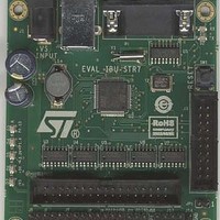
... The EVAL_IBU-STR7 is a control interface board dedicated to the EVAL6460 control; it communicates with the PC and the flexSPIN evaluation software via a serial port (RS232). The EVAL6460 is connected to the STR7 interface board via a standard 34-pin ribbon cable interface. The control interface board is based on the STR711FR2, an ARM-powered 32-bit microcontroller with embedded high-speed single voltage Flash memory and high-speed RAM ...
Page 12
... The EVAL6460 controlled by the EVAL_IBU-STR7 Figure 6. EVAL_IBU-STR7 schematic board 12/34 Doc ID 16599 Rev 2 AN3097 ...
Page 13
... AN3097 3.1 Board connection and configuration In this section the configuration of the EVAL6460 board, how to connect the board supply, loads, and interface through the EVAL_IBU-STR7 is shown. 3.1.1 Jumper configuration 1. Startup configuration (refer to the L6460 datasheet - startup configurations section). Figure 7. Jumper startup configuration All the jumpers are kept low: the single-device major mode is set ...
Page 14
... The EVAL6460 controlled by the EVAL_IBU-STR7 3. nAwake driving source (refer to the L6460 section - nAWAKE pin) Figure 9. nAwake driving source Here in the "master" position, place it in the alternative position on the board used as slave. 4. Awake input (refer to the L6460 section - nAWAKE pin) Figure 10. Awake input This jumper must be closed on the master board, in this way the nAWAKE pin can be driven by the EVAL_IBU-STR7 board ...
Page 15
... Connect the EVAL_IBU-STR7 power supply (VS - J2): the VS LED turns-on together with the 3.3 V LED (3 generated on board). VS must be in the range of 4 The EVAL_IBU-STR7 supply may also be provided by a USB cable. The 5 V LED turns-on to display the presence of the USB supply. 3.2 Starting flexSPIN evaluation software First of all copy the files - executable and COMset - in the same directory. The " ...
Page 16
... The EVAL6460 controlled by the EVAL_IBU-STR7 Figure 13. FlexSPIN evaluation software - start window Moving the mouse cursor over the image, a brief description of highlighted areas appears on the bottom line. Clicking on some areas, a window appears with the related electrical schematic. 3.2.1 How to turn-on the VswDrv regulator The integrated switching regulator controller is able to drive an external FET to implement a switching buck regulator ...
Page 17
... The DAC output is connected to GPIO8, and then in order to use it to change the VswDrv voltage, the JP8 must be closed (VSWDRV_FB connected to GPIO8). In the first software window click the L6460 device and then the "Current DAC" button, the following window appears The EVAL6460 controlled by the EVAL_IBU-STR7 15). (Figure 17). ...
Page 18
... The EVAL6460 controlled by the EVAL_IBU-STR7 Figure 17. Current DAC block diagram Here you can set the LSB typical current and the relative full scale typical current, then by writing the DAC value in the text box you can set the amount of current sink by the feedback pin of the switching regulator ...
Page 19
... During the startup procedure the bridges are in high impedance status and after they can be enabled through the SPI. In the first software window click the L6460 device and then the "Bridge 3" or "Bridge 4" button, the following window appears The EVAL6460 controlled by the EVAL_IBU-STR7 (Figure 20). Doc ID 16599 Rev 2 ...
Page 20
... The EVAL6460 controlled by the EVAL_IBU-STR7 Figure 20. Bridge 3 and 4 configuration In this window you can set the use of bridges 3 and 4: the default configuration allows the choosing of the output driving as mentioned for bridge 1 and 2. Clicking on one of the "Set configuration and enable" buttons and then on the "PWM3 - PWM4" button, the following window appears Figure 21 ...
Page 21
... If you want to drive a stepper motor click one of the buttons connected to the "stepper controller" box as shown in selected. Push one of the "Set configuration and enable" buttons. Figure 22. Bridge 3 and 4 configuration: stepper controller The EVAL6460 controlled by the EVAL_IBU-STR7 Figure 22; all the four connections to bridges 3 and 4 are Doc ID 16599 Rev 2 ...
Page 22
... The EVAL6460 controlled by the EVAL_IBU-STR7 In this window select "Config" under the "Stepper controller" rectangle, the "Bipolar Stepper Configuration" appears. In this window it is possible to set some parameters: ● Decay mode ● Offtime ● Blanking time ● Voltage reference for the current control ● ...
Page 23
... In the first software window click the L6460 device and then the "GPIOs" button, the following window appears The EVAL6460 controlled by the EVAL_IBU-STR7 (Figure 25). Doc ID 16599 Rev 2 ...
Page 24
... The EVAL6460 controlled by the EVAL_IBU-STR7 Figure 25. GPIOs block diagram On the top part there are the logic values read from each GPIO. To read again push the "refresh" button. By pushing the "Adc" button you can read the voltage value of each GPIO and convert it using the internal A-to-D converter ...
Page 25
... GPIO pin therefore the event can be signaled directly to the external circuits. In the first software window click the L6460 device and then the "IntCtrl" button, the following window appears The EVAL6460 controlled by the EVAL_IBU-STR7 ). The purpose of this circuit is to prevent the System (Figure 28) ...
Page 26
... The EVAL6460 controlled by the EVAL_IBU-STR7 Figure 28. Interrupt controller diagram Here you can choose the events that can cause an interrupt signal. 3.2.7 How to put the device into "low power" condition and awaken it When in normal operating mode, the microcontroller can place the L6460 in "low power mode" ...
Page 27
... Figure 30. Low power switch 1 enable By pushing the 'refresh' button you can check the pin voltage value. To open the switch set the connection as in The EVAL6460 controlled by the EVAL_IBU-STR7 supply. They are intended to provide and remove the power supply to Figure 31. ...
Page 28
... The EVAL6460 controlled by the EVAL_IBU-STR7 Figure 31. Low power switch 1 disable 3.2.10 How to measure an input voltage using A-D converter The L6460 integrates and makes a general purpose multi-input channel 3.3 V analog to digital converter (ADC) accessible via the SPI. In the first software window click the L6460 device and then the ADC button, the A-D window appears Figure 32 ...
Page 29
... L6460 includes a sequencer tool able to configure the device registers and program some command sequences. In the first software window click the L6460 device and then the "SPI" button, in the SPI window push the "Sequencer" button, the following window appears The EVAL6460 controlled by the EVAL_IBU-STR7 (Figure 34). Doc ID 16599 Rev 2 (Figure 35) ...
Page 30
... The EVAL6460 controlled by the EVAL_IBU-STR7 Figure 35. FlexSPIN sequencer window With this tool you can configure all device registers and program some command sequences to drive the L6460. ● Button description: – Browse: to set the file location to load – Save as: to save a sequence. The default format for the sequences is "txt". The sequence is saved in ASCII format and it can be modified with a text editor – ...
Page 31
... Manager" button in the L6460 window button, the value read starts to appear in the graph: yellow is sensor 1 and cyan is sensor 2 (time division 2 seconds). The EVAL6460 controlled by the EVAL_IBU-STR7 (Figure 36). By pushing the "Start Thermometer" Doc ID 16599 Rev 2 ...
Page 32
... The EVAL6460 controlled by the EVAL_IBU-STR7 Figure 36. Thermal manager window 3.2.14 How to work in master - slave configuration 1. Configure the slave board as described: – JP1 in slave position – Configuration jumpers: JP2 high, JP3 open, JP4 low – Set the ID jumper: JP5 high and JP6 low – ...
Page 33
AN3097 4 Revision history Table 4. Document revision history Date 03-May-2010 19-May-2010 Revision 1 Initial release 2 Modified: Figure 10, Doc ID 16599 Rev 2 Revision history Changes 11 and 12 33/34 ...
Page 34
... Information in this document is provided solely in connection with ST products. STMicroelectronics NV and its subsidiaries (“ST”) reserve the right to make changes, corrections, modifications or improvements, to this document, and the products and services described herein at any time, without notice. All ST products are sold pursuant to ST’s terms and conditions of sale. ...