PIC-P40-USB Olimex Ltd., PIC-P40-USB Datasheet
PIC-P40-USB
Specifications of PIC-P40-USB


Related parts for PIC-P40-USB


PIC-P40-USB Summary of contents
Page 1
... PIC-P40-USB development board Copyright(c) 2007, OLIMEX Ltd, All rights reserved Users Manual Rev.A, June 2007 ...
Page 2
... INTRODUCTION: PIC-P40-USB board was designed in mind to create board which to allow easy interface for your embedded projects to computers with USB. It’s based around the popular FTDI chips FT232. Some of you will say: wait a minute why to use additional expensive chip to interface my PIC to USB when I have seen on Microchip’s web ...
Page 3
... ON, when RE1 port is set to “1” LED will go OFF. PIC-P40-USB have handy GND pin for connection to oscilloscope. All modem signals from FT232 are provided and could be used. PIC-P40-USB have socket for I2C EEPROM which are connected to RC4-SDA and RC3-SCL On the schematic you will see PGM_SEL jumper, this is necessary ...
Page 4
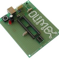
FEATURES: • ICSP/ICD connector for programming and debugging • FT232 USB-to-RS232 converter • DIL40 microcontroller socket • DIL8 EEPROM socket • Quartz crystal 20Mhz • LED to RE1 through jumper • user Button to RE2 • Reset button and circuit ...
Page 5
HARDWARE: ...
Page 6
... COM port. When you open Hyperterminal on your host PC computer with 9600 bps, 8 data bit, 1 stop bit, No flow control the PIC-P40-USB every character you type on the hyperterminal will be printed back with “*” i.e. if you type “abc” you will receive “a*b*c*”. ...
Page 7
... ORDER CODE: PIC-P40-USB PIC-P40-USB/PCB How to order? You can order to us directly or by any of our distributors. Check our web Revision history: REV.A - create June 2007 – assembled and tested (no kit, no soldering required) – blank PCBs only www.olimex.com/dev for more info. ...
Page 8
... This document is intended only to assist the reader in the use of the product. OLIMEX Ltd. shall not be liable for any loss or damage arising from the use of any information in this document or any error or omission in such ...