PIC-P40-USB Olimex Ltd., PIC-P40-USB Datasheet - Page 3
PIC-P40-USB
Manufacturer Part Number
PIC-P40-USB
Description
MCU, MPU & DSP Development Tools PROTOTYPE BRD ICSP/ ICD ENABLED 40 PIN
Manufacturer
Olimex Ltd.
Datasheet
1.PIC-P40-USB.pdf
(8 pages)
Specifications of PIC-P40-USB
Processor To Be Evaluated
40 Pin PIC Devices
Interface Type
USB, ICSP
Dimensions
100 mm x 80 mm
Operating Supply Voltage
3.3 V, 5 V
Silicon Manufacturer
Microchip
Core Architecture
PIC
Kit Contents
Board
Features
I2C EEPROM Socket, USB To RS232 FT232 Converter
Rohs Compliant
Yes
Lead Free Status / RoHS Status
Lead free / RoHS Compliant
Other names
1776342 52R3658


The on-board ICSP connector allow you to program the PIC on the
board without pulling it of the socket, by ICSP programmer like PIC-
MCP, PIC-MCP-USB, PIC-PG1, PIC-PG2, PIC-PG3, PIC-PG4 or to
program and debug it with PIC-ICD2, PIC-ICD2-POCKET or PIC-ICD2-
TINY.
IMPORTANT: all programmers provide power supply through
ICSP connector during the programming PIC-P40-USB should not be
connected to USB. Of course PIC-ICD2 have option to not power the
target circuit and this option should be used when you debug your
application while connected to USB.
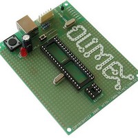
The oscillator circuit is made with 20 Mhz crystal oscillator, so you
can run your PIC at maximum performance.
The RESET circuit is made with simple RC circuit. Note that RESET
button should not be pressed while you program or debug the PIC!
PIC-P40-USB have user button for user input connected to PIC
microcontroller’s RE2 port. When RE2 port is initialized as INPUT you
will read “0” when the button is pressed and “1” when it is depressed.
Status LED is connected via jumper to PIC microcontroller’s RE1 port.
When your RE1 port is initialized as OUTPUT and set to “0” LED will
go ON, when RE1 port is set to “1” LED will go OFF.
PIC-P40-USB have handy GND pin for connection to oscilloscope.
All modem signals from FT232 are provided and could be used.
PIC-P40-USB have socket for I2C EEPROM which are connected to
RC4-SDA and RC3-SCL
On the schematic you will see PGM_SEL jumper, this is necessary
because some PICs use RB3 for ICSP-PGM signal others RB5, this is
done by smd jumper on the back side of the board which is soldered in
position RB3 by default (PIC18F877 which is used for the demo code),
if your PIC use RB5 you should connect this jumper properly.
Related parts for PIC-P40-USB
Image
Part Number
Description
Manufacturer
Datasheet
Request
R

Part Number:
Description:
MCU, MPU & DSP Development Tools PROTOTYPE BRD FOR 40 PIN PIC
Manufacturer:
Olimex Ltd.
Datasheet:


Part Number:
Description:
Daughter Cards & OEM Boards PIC-BEE XBEE RADIO INTERFACE
Manufacturer:
Gravitech
Datasheet:

Part Number:
Description:
MCU, MPU & DSP Development Tools PROTOTYPE BRD FOR 28 PIN PIC
Manufacturer:
Olimex Ltd.
Datasheet:
Part Number:
Description:
Development Boards & Kits - PIC / DSPIC MINI PROTOTYPE BRD FOR 8 PIN PIC
Manufacturer:
Olimex Ltd.

Part Number:
Description:
MCU, MPU & DSP Development Tools PROTOTYPE BRD FOR 18 PIN PIC
Manufacturer:
Olimex Ltd.
Datasheet:

Part Number:
Description:
DEVELOPMENT BOARD FOR 18 PIN PIC MICROCONTROLLERS
Manufacturer:
Olimex Ltd.
Datasheet:
Part Number:
Description:
Development Boards & Kits - PIC / DSPIC PROTOTYPE BRD FOR PIC18F26J50
Manufacturer:
Olimex Ltd.

Part Number:
Description:
Microcontroller & Microprocessor Development Tools TCP-IP DEV BRD PIC32MX460F512
Manufacturer:
Olimex Ltd.
Datasheet:

Part Number:
Description:
Microcontroller & Microprocessor Development Tools PROTOTYPE BOARD TMS320F28027
Manufacturer:
Olimex Ltd.
Datasheet:

Part Number:
Description:
Microcontroller & Microprocessor Development Tools HDR BRD FOR LPC3131
Manufacturer:
Olimex Ltd.
Datasheet:

Part Number:
Description:
Microcontroller & Microprocessor Development Tools MP3 PLYR MOD WITH VS1002
Manufacturer:
Olimex Ltd.
Datasheet:
Part Number:
Description:
Microcontroller & Microprocessor Development Tools MP3 PLYR MOD BAT WITH VS1002
Manufacturer:
Olimex Ltd.
Datasheet: