HM226-T Hendon Semiconductors, HM226-T Datasheet - Page 8
HM226-T
Manufacturer Part Number
HM226-T
Description
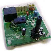
Switch Modules & Development Tools IES5541A demoboard Sensor Input Control
Manufacturer
Hendon Semiconductors
Datasheet
1.HM226-T.pdf
(15 pages)
Specifications of HM226-T
Description/function
Relay Switch Demo Board
Board Size
70 mm x 61 mm
Maximum Operating Temperature
+ 70 C
Minimum Operating Temperature
0 C
Supply Current
10 A
For Use With/related Products
IES5541A
Lead Free Status / RoHS Status
Lead free / RoHS Compliant


7
This section describes the circuit design approach used in
application of the IES5541A relay driver IC. In the HM226
there are options to satisfy different application needs and
temperature ranges.
7.1 Mains Supply Voltage
The HM226 circuit using the IES5541A have been
designed for Australian standards, where the normal
supply voltage is 230 Volts. However the IES5541A is
interfaced to the mains supply by a number of high voltage
resistors which can be selected to suit the design supply
voltage range.
The considerations involved in choosing the power supply,
SCR and triac drive components are the current draw of
the IES5541A, SCR and triac.
At the lowest value of the supply voltage there must be
sufficient supply current to power the IES5541A, and to
provide the gate current drive for the triac and SCR. When
the supply is at its highest, then the power dissipation of
the power supply resistor(s) must not be excessive.
7.2 Mains Rated Resistors
The power supply resistors, and those resistors in the
temperature sensing circuit which carry most of the mains
supply voltage should be chosen to give guaranteed
performance with high ac voltages. Mains rated resistors,
such as the Vishay VR37 and VR25 series or the Phoenix
Passive Components HVR25 and HVR37 series are
strongly recommended. Although standard metal film
resistors may be able to withstand the nominal supply
voltage they can become unreliable when subject to the
normal mains transients which are known to occur.
7.3 Temperature Control Shaft Rotation
The clip-in potentiometer shaft for adjusting the set
temperature or duty cycle can be either inserted through a
hole in the printed circuit board, or directly into the
potentiometer from the component side. Depending on
how the board is mounted and which surface faces
forward, the direction of rotation of the potentiometer will
vary.
2007 Dec 11, Revision 5.0
CIRCUIT DESCRIPTION
8
Protected Relay Switching Module
7.4 Choice of Thermistor
It is necessary to choose a thermistor which has a
resistance of at least 1,000 Ω at the operating
temperature, otherwise the voltage across the thermistor
will be too small to provide accurate and adequate
sensitivity. It is also important to ensure that the thermistor
can be mounted in a way that is electrically safe, is
protected from the access of moisture, and which provides
good thermal contact to the intended thermal measuring
point.
7.5 Thermistor Mounting Considerations
As the thermistor is electrically live to mains voltages it
must be adequately insulated for use in each application.
A range of insulated thermistors are available, and there
are a number of important issues which must be
considered in mounting them.
The best way in which to mount the thermistor is to clamp
along the length of the lead for about 50 mm starting just
clear of the sensing “head” of the lead. Ideally the plastic
head of the leaded thermistor should all be clear of the
mounting clamp by a distance of at least 1 to 5 mm. The
sensing head of an insulated leaded thermistor should
never be clamped.
Engineering Sample Information
HM226 - L / T
Related parts for HM226-T
Image
Part Number
Description
Manufacturer
Datasheet
Request
R

Part Number:
Description:
Switch Modules & Development Tools IES5541A demoboard Logic Input Control
Manufacturer:
Hendon Semiconductors
Datasheet:

Part Number:
Description:
General Purpose Triggering Circuit
Manufacturer:
Hendon Semiconductors
Datasheet:
Part Number:
Description:
LED Drivers 1-3.5V 1W LED Boost Driver
Manufacturer:
Hendon Semiconductors
Datasheet:
Part Number:
Description:
Power Management Modules & Development Tools OM5428 demoboard
Manufacturer:
Hendon Semiconductors
Datasheet:
Part Number:
Description:
Power Management Modules & Development Tools OM5448 demoboard
Manufacturer:
Hendon Semiconductors
Part Number:
Description:
Temperature Sensor Development Tools OM1682A demoboard
Manufacturer:
Hendon Semiconductors
Datasheet:

Part Number:
Description:
Triacs Phase Controller
Manufacturer:
Hendon Semiconductors
Datasheet:

Part Number:
Description:
Buffers & Line Drivers 2.7-5.5V 4.3mA 90ns 400-1000kHz
Manufacturer:
Hendon Semiconductors
Datasheet:

Part Number:
Description:
Buffers & Line Drivers Buffered 4-Chan Bus Switch
Manufacturer:
Hendon Semiconductors
Datasheet:
Part Number:
Description:
Buffers & Line Drivers 2.7-5.5V 6.1mA 45ns 400kHz
Manufacturer:
Hendon Semiconductors
Datasheet:
Part Number:
Description:
Buffers & Line Drivers 2.7-5.5V Simple 2 Wire Buffer
Manufacturer:
Hendon Semiconductors
Datasheet:

Part Number:
Description:
Buffers & Line Drivers 2.7-5.5V 4.3mA 90ns 400-1000kHz
Manufacturer:
Hendon Semiconductors
Datasheet:
Part Number:
Description:
Buffers & Line Drivers 2.7-5.5V Simple 2 Wire Buffer
Manufacturer:
Hendon Semiconductors
Datasheet:
Part Number:
Description:
Buffers & Line Drivers 2.7-5.5V 6.1mA 45ns 400kHz
Manufacturer:
Hendon Semiconductors
Datasheet:
Part Number:
Description:
Buffers & Line Drivers 2.7-5.5V Simple 2 Wire Buffer
Manufacturer:
Hendon Semiconductors
Datasheet: