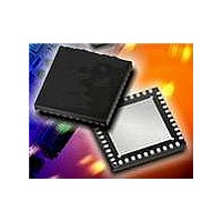
MAX2067ETL+ Maxim Integrated Products, MAX2067ETL+ Datasheet - Page 17

MAX2067ETL+
Manufacturer Part Number
MAX2067ETL+
Description
RF Amplifier IC VGA PROG ANALG-EP h-Linearity, Serial-
Manufacturer
Maxim Integrated Products
Datasheet
1.MAX2067EVKIT.pdf
(23 pages)
Specifications of MAX2067ETL+
Bandwidth
1000 MHz
Mounting Style
SMD/SMT
Operating Supply Voltage
5 V
Supply Current
72 mA
Maximum Power Dissipation
6.5 W
Maximum Operating Temperature
+ 85 C
Minimum Operating Temperature
- 40 C
Package / Case
TQFN-40
Lead Free Status / RoHS Status
Lead free / RoHS Compliant
1, 16, 19, 22, 24–28,
30, 31, 33–36
8–15, 23, 29
PIN
17
18
20
21
32
37
38
39
40
—
2
3
4
5
6
7
______________________________________________________________________________________
ANALOG_VCTRL
VCC_ANALOG
VREF_SELECT
VDD_LOGIC
ATTEN_OUT
AMP_OUT
VCC_AMP
ATTEN_IN
VDAC_EN
VREF_IN
AMP_IN
NAME
DATA
RSET
GND
GND
CLK
CS
EP
50MHz to 1000MHz High-Linearity,
Ground
DAC Reference Voltage Selection Logic Input. Logic 1 = internal DAC reference
voltage, Logic 0 = external DAC reference voltage. Logic input disabled (don’t care)
when VDAC_EN = Logic 0.
DAC Enable/Disable Logic Input. Logic 0 = disable DAC circuit, Logic 1 = enable
DAC circuit.
SPI Data Digital Input
SPI Clock Digital Input
SPI Chip-Select Digital Input
Digital Logic Supply Input. Connect to the digital logic power supply, V
to GND with a 10nF capacitor as close as possible to the pin.
Ground. See the Pin-Compatibility Considerations section.
Driver Amplifier Output (50Ω). See the Typical Application Circuit for details.
Driver Amplifier Bias-Setting Input. See the External Bias section.
Driver Amplifier Input (50Ω). See the Typical Application Circuit for details.
Driver Amplifier Supply Voltage Input. Connect to the V
GND with 1000pF and 10nF capacitors as close as possible to the pin, with the
smaller value capacitor closer to the part.
Analog Attenuator Output. Internally matched to 50Ω. Requires an external DC-
blocking capacitor.
Analog Attenuator Input. Internally matched to 50Ω. Requires an external DC-
blocking capacitor.
Analog Bias and Control Supply Voltage Input. Bypass to GND with a 10nF
capacitor as close as possible to the pin.
Analog Attenuator Voltage-Control Input
External DAC Voltage Reference Input
Exposed Pad. Internally connected to GND. Connect EP to ground for proper RF
performance and enhanced thermal dissipation.
Serial/Analog-Controlled VGA
DESCRIPTION
CC
Pin Description
power supply. Bypass to
DD
, Bypass
17


