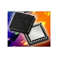
MAX2067ETL+ Maxim Integrated Products, MAX2067ETL+ Datasheet - Page 20

MAX2067ETL+
Manufacturer Part Number
MAX2067ETL+
Description
RF Amplifier IC VGA PROG ANALG-EP h-Linearity, Serial-
Manufacturer
Maxim Integrated Products
Datasheet
1.MAX2067EVKIT.pdf
(23 pages)
Specifications of MAX2067ETL+
Bandwidth
1000 MHz
Mounting Style
SMD/SMT
Operating Supply Voltage
5 V
Supply Current
72 mA
Maximum Power Dissipation
6.5 W
Maximum Operating Temperature
+ 85 C
Minimum Operating Temperature
- 40 C
Package / Case
TQFN-40
Lead Free Status / RoHS Status
Lead free / RoHS Compliant
50MHz to 1000MHz High-Linearity,
Serial/Analog-Controlled VGA
Bias currents for the driver amplifier are set and opti-
mized through external resistors. Resistors R1 and R1A
connected to RSET (pin 18) set the bias current for the
amplifier. The external biasing resistor values can be
increased for reduced current operation at the expense
of performance. See Tables 4 and 5 for details.
The MAX2067 is a simplified version of the MAX2065
analog/digital VGA. The MAX2067 does not contain a
digital attenuator and parallel inputs D0–D4. The asso-
ciated input/output pins are internally connected to
ground (Table 3). Ground the unused input/output pins
to optimize isolation. ( See the Typical Application
Circuit.)
The MAX2067 features an optional +3.3V supply voltage
operation with slightly reduced linearity performance.
The pin configuration of the MAX2067 has been opti-
mized to facilitate a very compact physical layout of the
device and its associated discrete components.
Table 4. Typical Application Circuit Component Values (HC Mode)
20
R2 (+3.3V applications only)
R3 (+3.3V applications only)
R4 (+5V applications and
using internal DAC only)
______________________________________________________________________________________
C3, C4, C6, C8, C9
C1, C2, C7, C12
DESIGNATION
C10, C11
R1, R1A
U1
L1
Pin-Compatibility Considerations
+5V and +3.3V Supply Voltage
Layout Considerations
VALUE
1000pF
470nH
150pF
47kΩ
10nF
10Ω
1kΩ
2kΩ
—
External Bias
40-pin thin QFN-EP
(6mm x 6mm)
SIZE
1008
0402
0402
0402
0402
0402
0402
0402
The exposed paddle (EP) of the MAX2067’s 40-pin thin
QFN-EP package provides a low thermal-resistance
path to the die. It is important that the PCB on which the
MAX2067 is mounted be designed to conduct heat
from the EP. In addition, provide the EP with a low-
inductance path to electrical ground. The EP must be
soldered to a ground plane on the PCB, either directly
or through an array of plated via holes.
Table 3. MAX2065/MAX2067 Pin
Comparison
PIN
10
11
12
13
14
15
23
29
8
9
Murata Mfg. Co., Ltd.
Murata Mfg. Co., Ltd.
Murata Mfg. Co., Ltd.
Maxim Integrated
Panasonic Corp.
Panasonic Corp.
Panasonic Corp.
Panasonic Corp.
Products, Inc.
Coilcraft, Inc.
VENDOR
ATTEN2_OUT
ATTEN2_IN
MAX2065
STATE_A
STATE_B
SER/PAR
D4
D3
D2
D1
D0
C0G ceramic capacitors
C0G ceramic capacitors
1008CS-471XJLC
DESCRIPTION
MAX2067ETL+
MAX2067
X7R
1%
1%
1%
1%
GND
GND
GND
GND
GND
GND
GND
GND
GND
GND


