TGA2511 TriQuint, TGA2511 Datasheet
TGA2511
Specifications of TGA2511
Available stocks


Related parts for TGA2511

TGA2511 Summary of contents
Page 1
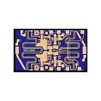
... P1dB is over 12dBm. The small size of 2 2.46mm allows ease of compaction into Multi- Chip-Modules (MCMs). The TGA2511 is 100% DC and RF tested on- wafer to ensure performance compliance. Lead-Free & RoHS compliant. Datasheet subject to change without notice TriQuint Semiconductor: www. triquint.com (972)994-8465 Fax (972)994-8504 Info-mmw@tqs.com Key Features • ...
Page 2
... TriQuint Semiconductor: www. triquint.com (972)994-8465 Fax (972)994-8504 Info-mmw@tqs.com TABLE I MAXIMUM RATINGS 1/ VALUE Gate Bias: [3.5 + (0.0125)(Id)] V Self Bias: [3.5 + (0.0360)(Id +0.5 V 240 dBm 1.56 W 200 ° C 320 ° C -65 to 150 ° C TABLE II C, Nominal) ° MIN. TYP. -30 -0.7 March 2010 © Rev A TGA2511 NOTES MAX. UNITS - ...
Page 3
... Output Return Loss, S22 Noise Figure, NF Output Power @ 1dB Gain Compression, P1dB OIP3 TriQuint Semiconductor: www. triquint.com (972)994-8465 Fax (972)994-8504 Info-mmw@tqs.com TABLE III 0 C Nominal) Gate Bias Self Bias 5.0 5.0 160 80 -0 1.3 1 March 2010 © Rev A TGA2511 UNITS GHz dBm dBm 3 ...
Page 4
... Channel Temperature ( C) TriQuint Semiconductor: www. triquint.com (972)994-8465 Fax (972)994-8504 Info-mmw@tqs.com TABLE IV θ θ θ θ (° ° ° ° C) (° ° ° ° C/W) 103.9 42.4 82.7 31.7 75 100 125 ° March 2010 © Rev A TGA2511 T m (HRS) 3.8E+6 4.1E+7 150 4 ...
Page 5
... Measured Fixtured Data Bias Conditions: Gate Bias 160 Frequency (GHz) Frequency (GHz) 5.0 4.5 4.0 3.5 3.0 2.5 2.0 1.5 1.0 0.5 0 Frequency (GHz) TriQuint Semiconductor: www. triquint.com (972)994-8465 Fax (972)994-8504 Info-mmw@tqs.com March 2010 © Rev A TGA2511 ...
Page 6
... Measured Fixtured Data Bias Conditions: Gate Bias 160 -10 -15 -20 -25 -30 - Frequency (GHz) Frequency (GHz -10 -15 -20 -25 -30 - Frequency (GHz) TriQuint Semiconductor: www. triquint.com (972)994-8465 Fax (972)994-8504 Info-mmw@tqs.com March 2010 © Rev A TGA2511 ...
Page 7
... Measured Fixtured Data Bias Conditions: Gate Bias 160 Frequency (GHz) Frequency (GHz Frequency (GHz) TriQuint Semiconductor: www. triquint.com (972)994-8465 Fax (972)994-8504 Info-mmw@tqs.com March 2010 © Rev A TGA2511 ...
Page 8
... Measured Fixtured Data Bias Conditions: Self Bias Frequency (GHz) Frequency (GHz) 5.0 4.5 4.0 3.5 3.0 2.5 2.0 1.5 1.0 0.5 0 Frequency (GHz) TriQuint Semiconductor: www. triquint.com (972)994-8465 Fax (972)994-8504 Info-mmw@tqs.com March 2010 © Rev A TGA2511 ...
Page 9
... Measured Fixtured Data Bias Conditions: Self Bias -10 -15 -20 -25 -30 - Frequency (GHz -10 -15 -20 -25 -30 - Frequency (GHz) TriQuint Semiconductor: www. triquint.com (972)994-8465 Fax (972)994-8504 Info-mmw@tqs.com March 2010 © Rev A TGA2511 ...
Page 10
... Measured Fixtured Data Bias Conditions: Self Bias Frequency (GHz Frequency (GHz) TriQuint Semiconductor: www. triquint.com (972)994-8465 Fax (972)994-8504 Info-mmw@tqs.com March 2010 © Rev A TGA2511 ...
Page 11
... March 2010 © Rev A TGA2511 1.955 1.897 (0.077) (0.075) 6 0.600 7 (0.024) 0.095 8 8 (0004) (0004) 2.050 1 ...
Page 12
... All DC connections may be brought in from either side of the chip (Use Pad 0.01uF external Cap is recommended on Drain Bias (Id = ~80mA) GaAs MMIC devices are susceptible to damage from Electrostatic Discharge. Proper precautions should be observed during handling, assembly and test. TriQuint Semiconductor: www. triquint.com (972)994-8465 Fax (972)994-8504 Info-mmw@tqs.com Vd 100pF RF Out March 2010 © Rev A TGA2511 12 ...
Page 13
... All DC connections may be brought in from either side of the chip (Use Pad and Pad 0.01uF external Caps are recommended on Drain line Bias (Id = ~80mA), Vctrl = 0 to +5V for Gain adjustment TriQuint Semiconductor: www. triquint.com (972)994-8465 Fax (972)994-8504 Info-mmw@tqs.com Vctrl Vd 100pF 100pF RF Out March 2010 © Rev A TGA2511 13 ...
Page 14
... Source connections (Pad 2, 3, 11, 12) are bonded to ground. All four bond wires are required for stability. Bias Vctrl = 0 to +5V for Gain adjustment Vg = Range, -0 typically ~ -0.1 will provide ~160mA of Id. TriQuint Semiconductor: www. triquint.com (972)994-8465 Fax (972)994-8504 Info-mmw@tqs.com Vctrl Vd 100pF 100pF 100pF RF Out March 2010 © Rev A TGA2511 14 ...
Page 15
... Aluminum wire should not be used. • Maximum stage temperature is 200 GaAs MMIC devices are susceptible to damage from Electrostatic Discharge. Proper precautions should be observed during handling, assembly and test. TriQuint Semiconductor: www. triquint.com (972)994-8465 Fax (972)994-8504 Info-mmw@tqs.com 0 C. March 2010 © Rev A TGA2511 0 C (30 seconds max). 15 ...