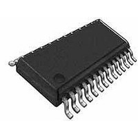
WM8741GEDS/V Wolfson Microelectronics, WM8741GEDS/V Datasheet - Page 22

WM8741GEDS/V
Manufacturer Part Number
WM8741GEDS/V
Description
Audio D/A Converter ICs Stereo DAC, High End
Manufacturer
Wolfson Microelectronics
Datasheet
1.WM8741GEDSV.pdf
(64 pages)
Specifications of WM8741GEDS/V
Mounting Style
SMD/SMT
Package / Case
SSOP-28
Lead Free Status / RoHS Status
Lead free / RoHS Compliant
Available stocks
Company
Part Number
Manufacturer
Quantity
Price
Company:
Part Number:
WM8741GEDS/V
Manufacturer:
Wolfson Microelectronics
Quantity:
1 881
WM8741
w
PCM DIGITAL AUDIO INTERFACE
Audio data is applied to the DAC system via the Digital Audio Interface. Five popular interface
formats are supported:
All five formats require the MSB to be transmitted first, and support word lengths of 16, 20, 24 and 32
bits, with the exception that 32 bit data is not supported in right justified mode. DIN and LRCLK may
be configured to be sampled on the rising or falling edge of BCLK by adjusting register bits LRP and
BCP.
In left justified, right justified and I
on the DIN input pin. Stereo audio data is time multiplexed on DIN, with LRCLK indicating whether
the left or right channel is present.
beginning or end of the data words.
The minimum number of BCLK periods per LRCLK period is two times the selected word length.
LRCLK must be high for a period equal to the minimum number of BCLK periods, and low for a
minimum of the same period. Any mark-to-space ratio on LRCLK is acceptable provided the above
requirements are met.
The WM8741 will automatically detect when data with a LRCLK period of exactly 32 BCLKs is
received, and select 16-bit mode. This overrides any previously programmed word length. The
operating word length will revert to a programmed value only if a LRCLK period other than 32 BCLKs
is detected.
In DSP mode A or DSP mode B, the data is time multiplexed onto DIN. LRCLK is used as a frame
sync signal to identify the MSB of the first word. The minimum number of BCLKs per LRCLK period
is two times the selected word length. Any mark to space ratio is acceptable on LRCLK provided the
rising edge is correctly positioned.
LEFT JUSTIFIED MODE
In left justified mode, the MSB is sampled on the first rising edge of BCLK following a LRCLK
transition. LRCLK is high during the left data word and low during the right data word.
Figure 14 Left Justified Mode Timing Diagram
•
•
•
•
•
Left Justified mode
Right Justified mode
I
DSP mode A
DSP mode B
2
S mode
2
S audio interface modes, the digital audio interface receives data
LRCLK is also used as a timing reference to indicate the
PD, Rev 4.2, October 2009
Production Data
22


