HR30-6P-T02 Hirose Electric Co Ltd, HR30-6P-T02 Datasheet - Page 10
HR30-6P-T02
Manufacturer Part Number
HR30-6P-T02
Description
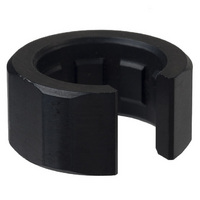
TOOL BACK SHELL TIGHTING COLLAR
Manufacturer
Hirose Electric Co Ltd
Series
HR30r
Type
Tightening Collarr
Datasheet
1.HR30-6R-C71.pdf
(12 pages)
Specifications of HR30-6P-T02
Accessory Type
Collar
Color
Silver
Product
Crimping, Stripping & Cutting Tools & Drills
Description/function
Tightens backshell to specified torque
Fits Cable/wire
26-30 AWG
Wire Gauge Min (awg)
26
Wire Gauge Range
26-30
For Use With/related Products
HR30 Series Backshells
For Use With
HR594 - CONN JACK 6POS MALE SOLDERHR593 - CONN JACK 6POS MALE SOLDERHR583 - CONN PLUG 6POS MALE SOLDERHR582 - CONN PLUG 6POS FEMALE SOLDERHR581 - CONN PLUG 3POS FEMALE SOLDERHR580 - CONN PLUG 6POS MALE SOLDERHR579 - CONN PLUG 6POS FEMALE SOLDERHR578 - CONN PLUG 3POS FEMALE SOLDER
Lead Free Status / RoHS Status
Lead free / RoHS Compliant
Features
-
Shell Size - Insert
-
Lead Free Status / Rohs Status
Lead free / RoHS Compliant
Other names
*HR30-6P-T02
H9952
HR306PT02
H9952
HR306PT02


The product information in this catalog is for reference only. Please request the Engineering Drawing for the most current and accurate design information.
All non-RoHS products have been discontinued, or will be discontinued soon. Please check the products status on the Hirose website RoHS search at www.hirose-connectors.com, or contact your Hirose sales representative.
10
BAssembly Procedures
1
2
Thread the back shell, strain relief, seal bushing, spring and push/pull locking collar over the cable as shown above.
Solder type
1. Pre-solder the exposed cable conductors (dia. A). The diameter of the pre-soldered conductors should not exceed 0.7
2. Insert the insulator body over the applicable solder termination fixture.
3. Insert the pre-soldered conductors in the contact soldering pot and solder them in place.
Crimp type
1. Crimp the applicable contact to the stripped conductor. Use correct crimp tools. Verify the dimensions and crimp
2. Insert the contact into the appropriate opening in the insulator body.
3. Verify fully seated position by applying a slight pull force on the conductor. The contact should remain in place.
mm for 6 contact plug and 1.0 mm for 3 contact plug.
Soldering iron temperature should be
configuration.
Re-insert if not seated.
Plug Assembly Sequence
applied for 3-4 second.
Solder type : 3 and 6 pos.
Solder type : 12 pos.
Crimp type : 10 and 12 pos.
2
2 mm
2 mm
-0
-0.5
A
mm
5.5 mm max.
15
10 mm max.
B
20 mm
Related parts for HR30-6P-T02
Image
Part Number
Description
Manufacturer
Datasheet
Request
R

Part Number:
Description:
CONN PLUG 3POS FEMALE SOLDER
Manufacturer:
Hirose Electric Co Ltd
Datasheet:

Part Number:
Description:
CONN PLUG 6POS MALE SOLDER
Manufacturer:
Hirose Electric Co Ltd
Datasheet:
Part Number:
Description:
CONN PLUG 6POS MALE SOLDER
Manufacturer:
Hirose Electric Co Ltd
Datasheet:

Part Number:
Description:
CONN DUST CAP FOR 3&6POS PLUG
Manufacturer:
Hirose Electric Co Ltd
Datasheet:
Part Number:
Description:
CONN DUST CAP FOR 3&6POS PLUG
Manufacturer:
Hirose Electric Co Ltd
Datasheet:

Part Number:
Description:
Conn Rectangular PL 14 POS 2.54mm Crimp RA Cable Mount
Manufacturer:
Hirose Electric Co Ltd
Part Number:
Description:
Conn Shrouded Header HDR 10 POS 2mm Solder ST SMD Embossed T/R
Manufacturer:
Hirose Electric Co Ltd
Datasheet:
Part Number:
Description:
DF11-20DP-2DSA(24)
Manufacturer:
Hirose Electric Co Ltd
Datasheet:
Part Number:
Description:
Conn Shrouded Header HDR 6 POS 2mm Solder ST Thru-Hole Bag
Manufacturer:
Hirose Electric Co Ltd
Datasheet:
Part Number:
Description:
Conn Shrouded Header HDR 8 POS 2mm Solder ST Thru-Hole Tube
Manufacturer:
Hirose Electric Co Ltd
Datasheet:
Part Number:
Description:
Conn Shrouded Header HDR 26 POS 2mm Solder ST SMD
Manufacturer:
Hirose Electric Co Ltd
Datasheet:
Part Number:
Description:
Conn Shrouded Header HDR 22 POS 2mm Solder ST SMD
Manufacturer:
Hirose Electric Co Ltd
Part Number:
Description:
Conn Shrouded Header HDR 22 POS 2mm Solder ST SMD
Manufacturer:
Hirose Electric Co Ltd
Part Number:
Description:
2mm 22w Wire to Board IDC Crimp Connector
Manufacturer:
Hirose Electric Co Ltd