DE1E3KX222MA4BL01 Murata, DE1E3KX222MA4BL01 Datasheet - Page 20
DE1E3KX222MA4BL01
Manufacturer Part Number
DE1E3KX222MA4BL01
Description
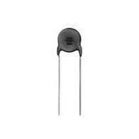
Ceramic Disc Capacitors 2200pF 20%
Manufacturer
Murata
Specifications of DE1E3KX222MA4BL01
Voltage Rating
250 Volts
Operating Temperature Range
- 25 C to + 125 C
Termination Style
Radial
Product
High Voltage Ceramic Disc Capacitors
Dimensions
9 mm Dia.
Capacitance
2200 pF
Tolerance
20 %
Temperature Coefficient
E
Lead Spacing
10 mm
Lead Free Status / RoHS Status
Lead free / RoHS Compliant
Available stocks
Company
Part Number
Manufacturer
Quantity
Price
Company:

Part Number:
DE1E3KX222MA4BL01
Manufacturer:
MURATA
Quantity:
10 000
Part Number:
DE1E3KX222MA4BL01
Manufacturer:
MURATA/村田
Quantity:
20 000


!Note
• This PDF catalog is downloaded from the website of Murata Manufacturing co., ltd. Therefore, it’s specifications are subject to change or our products in it may be discontinued without advance notice. Please check with our
• This PDF catalog has only typical specifications because there is no space for detailed specifications. Therefore, please approve our product specifications or transact the approval sheet for product specifications before ordering.
sales representatives or product engineers before ordering.
!Note
No.
16
18
19
20
17
*
1
"room condition" Temperature: 15 to 35°C, Relative humidity: 45 to 75%, Atmospheric pressure: 86 to 106kPa
Continued from the preceding page.
Humidity
Loading
Life
Flame Test
Robustness
of
Terminations
Temperature
and
Immersion
Cycle
• Please read rating and !CAUTION (for storage, operating, rating, soldering, mounting and handling) in this catalog to prevent smoking and/or burning, etc.
• This catalog has only typical specifications because there is no space for detailed specifications. Therefore, please approve our product specifications or transact the approval sheet for product specifications before ordering.
Item
Appearance
Capacitance
Change
D.F.
I.R.
Dielectric
Strength
Appearance
Capacitance
Change
I.R.
Dielectric
Strength
Tensile
Bending
Appearance
Capacitance
Change
D.F.
I.R.
Dielectric
Strength
No marked defect
1000MΩ min.
Per Item 6
No marked defect
1000MΩ min.
Per Item 6
The capacitor flame discontinued as follows.
Lead wire should not be cut off. Capacitor should
not be broken.
No marked defect
1000MΩ min.
Per Item 6
Cycle
Char.
Char.
Char.
1 to 2
Char.
Char.
E
E
E
E
E
F
F
F
3
F
F
Capacitance Change
Capacitance Change
Capacitance Change
Specifications
Specifications
Specifications
Within ±20%
Within ±30%
Within ±20%
Within ±30%
Within ±20%
Within ±30%
Time (sec.)
D.F.V5.0%
D.F.V7.5%
D.F.V5.0%
D.F.V7.5%
15 max.
60 max.
DEJ Series Specifications and Test Methods
Apply the rated voltage for 500±12 hrs. at 40±2˚C in 90 to 95%
relative humidity.
Pre-treatment:
Post-treatment:
Apply a voltage of Table 2 for 1500 hrs. at 85±2˚C, relative
humidity 50% max.
Pre-treatment:
Post-treatment:
The capacitor should be subjected
to applied flame for 15 sec. and then
removed for 15 sec. until 3 cycles
are completed.
As shown in figure at right, fix the body of
capacitor, apply a tensile weight gradually to
each lead wire in the radial direction of capacitor
up to 10N and keep it for 10±1 sec.
Each lead wire should be subjected to 5N weight and then a
90° bend, at the point of egress, in one direction, return to
original position, and then apply a 90° bend in the opposite
direction at the rate of one bend in 2 to 3 sec.
The capacitor should be subjected to 5 temperature cycles,
then consecutively to 2 immersion cycles.
Pre-treatment:
Post-treatment:
Capacitor should be stored at 85±2˚C for 1 hr., then placed at
Capacitor should be stored for 1 to 2 hrs. at
Capacitor should be stored at 85±2˚C for 1 hr., then placed at
Capacitor should be stored for 4 to 24 hrs. at
Capacitor should be stored at 85±2˚C for 1 hr., then placed at
Capacitor should be stored for 4 to 24 hrs. at
1
1
1
room condition for 24±2 hrs. before initial measurements.
room condition for 24±2 hrs. before initial measurements.
room condition for 24±2 hrs.
AC500V(r.m.s.), except that once each hour the voltage
is increased to AC1000V(r.m.s.) for 0.1 sec.
Step
Step
1
2
1
2
3
4
Gas Burner: Inside Dia. 9.5
Temperature (ºC)
65+5/-0
Temperature (ºC)
0±3
<Temperature Cycle>
<Immersion Cycle>
Room temp.
Room temp.
Applied Voltage
Testing Method
-25+0/-3
85+3/-0
<Table 2>
Time
(min)
15
15
Cycle time: 5 cycle
Cycle time: 2 cycle
1
Immersion
room condition.
1
Time (min)
1
room condition.
room condition.
Water
Clean
water
water
Salt
W
30
30
3
3
Capacitor
Flame
(in mm)
C85E.pdf
19
06.6.1
5
Related parts for DE1E3KX222MA4BL01
Image
Part Number
Description
Manufacturer
Datasheet
Request
R

Part Number:
Description:
Murata Microblower 20x20 DCDC Driver Board - Samples Only
Manufacturer:
Murata
Part Number:
Description:
357-036-542-201 CARDEDGE 36POS DL .156 BLK LOPRO
Manufacturer:
Murata
Datasheet:
Part Number:
Description:
Manufacturer:
Murata
Datasheet:
Part Number:
Description:
Manufacturer:
Murata
Datasheet:
Part Number:
Description:
Manufacturer:
Murata
Datasheet:
Part Number:
Description:
Manufacturer:
Murata
Datasheet:
Part Number:
Description:
Manufacturer:
Murata
Datasheet:
Part Number:
Description:
Manufacturer:
Murata
Datasheet:
Part Number:
Description:
Manufacturer:
Murata
Datasheet:
Part Number:
Description:
BLM21BD751SN1On-Board Type (DC) EMI Suppression Filters
Manufacturer:
Murata
Datasheet:
Part Number:
Description:
BLM15AG100SN1On-Board Type (DC) EMI Suppression Filters
Manufacturer:
Murata
Datasheet:
Part Number:
Description:
NFE31PT222Z1E9On-Board Type (DC) EMI Suppression Filters
Manufacturer:
Murata
Datasheet:
Part Number:
Description:
Chip Coil
Manufacturer:
Murata
Datasheet:
Part Number:
Description:
Chip Coil
Manufacturer:
Murata
Datasheet: