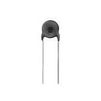
DE1E3KX222MA4BL01 Murata, DE1E3KX222MA4BL01 Datasheet - Page 38

DE1E3KX222MA4BL01
Manufacturer Part Number
DE1E3KX222MA4BL01
Description
Ceramic Disc Capacitors 2200pF 20%
Manufacturer
Murata
Specifications of DE1E3KX222MA4BL01
Voltage Rating
250 Volts
Operating Temperature Range
- 25 C to + 125 C
Termination Style
Radial
Product
High Voltage Ceramic Disc Capacitors
Dimensions
9 mm Dia.
Capacitance
2200 pF
Tolerance
20 %
Temperature Coefficient
E
Lead Spacing
10 mm
Lead Free Status / RoHS Status
Lead free / RoHS Compliant
Available stocks
Company
Part Number
Manufacturer
Quantity
Price
Company:
Part Number:
DE1E3KX222MA4BL01
Manufacturer:
MURATA
Quantity:
10 000
Part Number:
DE1E3KX222MA4BL01
Manufacturer:
MURATA/村田
Quantity:
20 000
!Note
• This PDF catalog is downloaded from the website of Murata Manufacturing co., ltd. Therefore, it’s specifications are subject to change or our products in it may be discontinued without advance notice. Please check with our
• This PDF catalog has only typical specifications because there is no space for detailed specifications. Therefore, please approve our product specifications or transact the approval sheet for product specifications before ordering.
sales representatives or product engineers before ordering.
!Note
No.
12
13
14
15
*
1
"room condition" Temperature: 15 to 35°C, Relative humidity: 45 to 75%, Atmospheric pressure: 86 to 106kPa
Continued from the preceding page.
Soldering Effect
(Non-Preheat)
Soldering Effect
(On-Preheat)
Temperature
Cycle
Humidity (Under
Steady State)
• Please read rating and !CAUTION (for storage, operating, rating, soldering, mounting and handling) in this catalog to prevent smoking and/or burning, etc.
• This catalog has only typical specifications because there is no space for detailed specifications. Therefore, please approve our product specifications or transact the approval sheet for product specifications before ordering.
Item
Appearance
Capacitance
Change
Dielectric Strength
(Between Lead
Wires)
Appearance
Capacitance
Change
Dielectric Strength
(Between Lead
Wires)
Appearance
Capacitance
Change
D.F.
I.R.
Dielectric Strength
(Between Lead
Wires)
Appearance
Capacitance
Change
D.F.
I.R.
No marked defect
Within ±10%
Per item 4.
No marked defect
Within ±10%
Per item 4.
No marked defect
Within ±10%
0.4% max.
1000MΩ min.
Per item 4.
No marked defect
Within ±10%
0.4% max.
1000MΩ min.
Specifications
DEH Series Specifications and Test Methods
The lead wire should be immersed into the melted solder of
350±10°C up to about 1.5 to 2mm from the main body for
3.5±0.5 sec.
Pre-treatment:
Post-treatment:
Measurement order:
First the capacitor should be
stored at 120+0/-5°C for
60+0/-5 sec.
Then, as in figure, the lead wires
should be immersed solder of
260+0/-5°C up to 1.5 to 2.0mm
from the root of terminal for
7.5+0/-1 sec.
Pre-treatment:
Post-treatment:
Measurement order:
The capacitor should be subjected to 5 temperature cycles.
<Temperature cycle>
Pre-treatment:
Post-treatment:
Measurement order:
Set the capacitor for 500 +24/-0 hrs. at 40±2°C in 90 to 95%
relative humidity.
Pre-treatment:
Post-treatment:
Measurement order:
Capacitor should be stored at 125±3°C for 1 hr., then placed
at *room condition for 24±2 hrs. before initial measurements.
Capacitor should be stored for 24±2 hrs. at *room condition.
Dielectric strength -> Pre-treatment -> Capacitance ->
Soldering effect test -> Post-treatment ->
Capacitance
Capacitor should be stored at 125±3°C for 1 hr., then placed
at *room condition for 24±2 hrs. before initial measurements.
Capacitor should be stored for 24±2 hrs. at *room condition.
Dielectric strength -> Pre-treatment -> Capacitance ->
Soldering effect test -> Post-treatment ->
Capacitance
Capacitor should be stored at 125±3°C for 1 hr., then placed
at *
Capacitor should be stored for 24±2 hrs. at *
I.R.
D.F. -> Temperature cycle test -> Post-treatment ->
Capacitance
(Char. R [DC250V])
Capacitor should be stored at 125±3°C for 1 hr., then placed
at *
Capacitor should be stored for 1 to 2 hrs. at *
I.R. -> Pre-treatment -> Capacitance
Post-treatment -> Capacitance
(Char. R [DC250V])
1
1
room condition for 24±2 hrs. before initial measurements.
•
room condition for 24±2 hrs. before initial measurements.
Dielectric strength -> Pre-treatment -> Capacitance
•
•
•
Step
Dielectric strength (Char. R [DC250V])
Dielectric strength (Char. R [DC250V])
D.F.
1
2
3
4
•
I.R.
Temperature (°C)
Testing Method
Room Temp.
Room Temp.
•
Dielectric strength
125±3
-25±3
Continued on the following page.
•
D.F.
Cycle time: 5 cycle
Thermal
Screen
•
•
D.F. -> Humidity test ->
I.R.
Time (min)
30
30
1
3
3
1
room condition.
room condition.
Capacitor
Molten
Solder
1.5
to 2.0mm
•
C85E.pdf
37
06.6.1
7


