BLM18RK221SN1D Murata, BLM18RK221SN1D Datasheet - Page 195
BLM18RK221SN1D
Manufacturer Part Number
BLM18RK221SN1D
Description
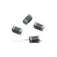
EMI/RFI Suppressors & Ferrites 0603 220ohms Digital Interface Tape
Manufacturer
Murata
Datasheet
1.BLM18RK221SN1D.pdf
(215 pages)
Specifications of BLM18RK221SN1D
Shielding
Unshielded
Test Frequency
100 MHz
Product
Chip Ferrite Beads
Impedance
220 Ohms
Tolerance
25 %
Maximum Dc Current
200 mAmps
Maximum Dc Resistance
0.3 Ohms
Operating Temperature Range
- 55 C to + 125 C
Package / Case
0603 (1608 metric)
Termination Style
SMD/SMT
Dc Resistance Max
0.3ohm
Dc Current Rating
200mA
Ferrite Mounting
SMD
Ferrite Case Style
0603 / 1608
Operating Temperature Max
+125°C
Operating Temperature Min
-55°C
Rohs Compliant
Yes
Lead Free Status / RoHS Status
Lead free / RoHS Compliant
Available stocks
Company
Part Number
Manufacturer
Quantity
Price
Company:

Part Number:
BLM18RK221SN1D
Manufacturer:
MURATA
Quantity:
240 000
Part Number:
BLM18RK221SN1D
Manufacturer:
MURATA/村田
Quantity:
20 000


!Note
• This PDF catalog is downloaded from the website of Murata Manufacturing co., ltd. Therefore, it’s specifications are subject to change or our products in it may be discontinued without advance notice. Please check with our
• This PDF catalog has only typical specifications because there is no space for detailed specifications. Therefore, please approve our product specifications or transact the approval sheet for product specifications before ordering.
sales representatives or product engineers before ordering.
!Note
BL01RN
BL02RN
BL03RN
Series
BL01RN_J
BL01RN_A
BL02RN1R3N1A
BL02RN2R3N1A
Minimum Quantity (Pcs.)
Taping Dimensions
• Please read rating and !CAUTION (for storage, operating, rating, soldering, mounting and handling) in this catalog to prevent smoking and/or burning, etc.
• This catalog has only typical specifications because there is no space for detailed specifications. Therefore, please approve our product specifications or transact the approval sheet for product specifications before ordering.
Pitch of component
Pitch of sprocket hole
Lead spacing
Hole center to lead
Hole center to component center
Offset of bead
Carrier tape width
Position of sprocket hole
Lead length between sprocket
hole and forming position
Protruding length
Diameter of sprocket hole
Lead Diameter
Total tape thickness
Deviation across tape, Deviation across tape rear
Cutting position of failure
Hold down tape width
Hold down tape position
0.8 max.
0 max.
1000
Bulk
500
500
P
P
1
1
P
P
Description
2
P
2
P
F
F
0
0
There is an excess bond stick on the wire.
*L BL01RN1A1F1J : 52+2/-1
P
P
BL01RN1A1E1A : 26+1.5/-0
L1
| L1 - L2 | V 1.5
Ammo Pack
8.0 max.
5 0.3
9.0 max.
*L
1000
1500
2000
D
D
0
0
ø0.60 0.05
L2
3.4 0.2
3.4 0.2
ø320mm Paper reel
3.2 min.
6.0 1.0
0.8 max.
Symbol
h
ød
1
W
W
W
ød
P
P
P
H
D
ød
W
P
F
, h
L
I
t
S
0
1
2
1
0
1
0
2
2000
—
—
h
2
h
1
S
1
S
Lead Length Number : N
Lead Length Number : Q
Lead Length Number : P
h
h
2
2
Dimension (mm)
+0.5 to –1.0
12.7 0.2
3.85 0.7
6.35 1.3
18.0 0.5
ø4.0 0.1
11.0
12.0 0.5
1.0 max.
5.0
9.0
0.7 0.2
1.5 1.5
ø0.60
12.7
1.0
+0.8
-0.2
+0
-0.5
0.0
+0
-1.0
0.0
BL02RN1R2p1A
BL02RN2R1p1A
BL03RN2R1p1A
Ferrite Beads Inductors Packaging
16.5 0.5
20.0 0.5
18.5 0.5
Product inclination S determines tolerance
Tape deviation in feeding direction
Include the offset caused by lead bend
Tape with deviation
BL02, BL03
BL02RN1R2/2R1, BL03
BL02, BL03
Including bonding tape thickness
P
P
1
1
P
P
1
P
2
2
P
P
P
F
F
2
0
0
P
There is an excess bond stick on the wire.
F
0
P
P
P
9.0 max.
7.5 max.
Remarks
8.3 max.
D
D
0
0
D
0
3.4 0.2
3.4 0.2
2.3 max.
ød
ød
ød
(in mm)
h
h
1
1
S
S
h
1
S
h
h
193
2
2
h
2
C31E.pdf
08.9.1
6
Related parts for BLM18RK221SN1D
Image
Part Number
Description
Manufacturer
Datasheet
Request
R

Part Number:
Description:
Murata Microblower 20x20 DCDC Driver Board - Samples Only
Manufacturer:
Murata
Part Number:
Description:
357-036-542-201 CARDEDGE 36POS DL .156 BLK LOPRO
Manufacturer:
Murata
Datasheet:
Part Number:
Description:
Manufacturer:
Murata
Datasheet:
Part Number:
Description:
Manufacturer:
Murata
Datasheet:
Part Number:
Description:
Manufacturer:
Murata
Datasheet:
Part Number:
Description:
Manufacturer:
Murata
Datasheet:
Part Number:
Description:
Manufacturer:
Murata
Datasheet:
Part Number:
Description:
Manufacturer:
Murata
Datasheet:
Part Number:
Description:
Manufacturer:
Murata
Datasheet:
Part Number:
Description:
BLM21BD751SN1On-Board Type (DC) EMI Suppression Filters
Manufacturer:
Murata
Datasheet:
Part Number:
Description:
BLM15AG100SN1On-Board Type (DC) EMI Suppression Filters
Manufacturer:
Murata
Datasheet:
Part Number:
Description:
NFE31PT222Z1E9On-Board Type (DC) EMI Suppression Filters
Manufacturer:
Murata
Datasheet:
Part Number:
Description:
Chip Coil
Manufacturer:
Murata
Datasheet:
Part Number:
Description:
Chip Coil
Manufacturer:
Murata
Datasheet: