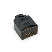
HEDM-5500#B11 Avago Technologies US Inc., HEDM-5500#B11 Datasheet - Page 7

HEDM-5500#B11
Manufacturer Part Number
HEDM-5500#B11
Description
Encoders 2 Channel 1000 CPR 4mm Film CW
Manufacturer
Avago Technologies US Inc.
Type
Optical Encoderr
Datasheet
1.HEDM-5500B11.pdf
(12 pages)
Specifications of HEDM-5500#B11
Number Of Channels
2
Mounting Style
Cable
Output
Quadrature with Index
Supply Voltage
5 V
Operating Temperature Range
- 40 C to + 100 C
Product
Kits
Pulses Per Revolution
1000 CPR
Termination Style
Solder Pin
Detents
No
Motion
Rotary
Index Output
Not Indexed
Encoder Signal
Digital
Built In Switch
No
Shaft Style
Round
Shaft Diameter (mm)
4mm
Operating Supply Voltage (typ)
5VDC
Operating Temperature Min Deg. C
-40C
Operating Temperature Max Deg. C
70C
Terminal Type
PC Pins
Lead Free Status / RoHS Status
Lead free / RoHS Compliant
Available stocks
Company
Part Number
Manufacturer
Quantity
Price
Mechanical Characteristics
Notes:
1. These are tolerances required of the user.
2. The HEDS-55X5 and 56X5, HEDM-5505, 5605 provide an 8.9 mm (0.35 inch) diameter hole through the housing for longer motor shafts. See
3. The HEDS-5540 and 5640 must be aligned using the aligning pins as specified in Figure 3, or using the alignment tool as shown in “Encoder
4. The recommended mounting screw torque for 2 screw and external ear mounting is 1.0 kg-cm (0.88 in-lbs). The recommended mounting screw
Electrical Interface
To insure reliable encodingperformance, the HEDS-
5540/5640 and HEDM-5540 three channel encoders
require 2.7 kΩ (± 10%) pull-up resistors on output pins 2, 3,
and 5 (Channels I, A, and B) as shown in Figure 1. These pull-
up resistors should be located as close to the encoder as
possible (within 4 feet). Each of the three encoder outputs
7
Parameter
Codewheel Fits These Standard
Shaft Diameters
Moment of Inertia
Required Shaft Length[2]
Bolt Circle[3]
Mounting Screw Size[4]
Encoder Base Plate Thickness
Hub Set Screw
Figure 1. Pull-up Resistors on HEDS-5X40 and HEDM-5540 Encoder Outputs.
Ordering Information.
Mounting and Assembly”. See also “Mounting Considerations. ”
torque for 3 screw mounting is 0.50 kg-cm (0.43 in-lbs).
Symbol
J
2 screw mounting
3 screw mounting
external mounting ears
2 screw mounting
3 screw mounting
external mounting ears
Dimension
2 3 4
5 6 8
5/32 1/8
3/16 1/4
0.6 (8.0 x 10
14.0 (0.55)
19.05
(0.750)
20.90
(0.823)
46.0
(1.811)
M 2.5 or (2-56)
M 1.6 or (0-80)
M 2.5 or (2-56)
0.33 (0.130)
(2-56)
can drive a single TTL load in this configuration. The HEDS-
5500, 5600, and HEDM-5500, 5600 two channel encoders
do not normally require pull-up resistors. However, 3.2
kΩ pull-up resistors on output pins 3 and 5 (Channels A
and B) are recommended to improve rise times, especially
when operating above 100 kHz frequencies.
-6
)
Tolerance
+0.000
-0.015
+0.0000
-0.0007
± 0.5
(± 0.02)
± 0.13
(± 0.005)
± 0.13
(± 0.005)
± 0.13
(± 0.005)
[1]
Units
mm
in
g-cm
mm (in.)
mm (in.)
mm (in.)
mm (in.)
mm (in.)
mm (in.)
mm (in.)
mm (in.)
(in.)
2
(oz-in-s
2
)


