Y92P-CXT4S Omron, Y92P-CXT4S Datasheet - Page 36
Y92P-CXT4S
Manufacturer Part Number
Y92P-CXT4S
Description
Mounting Hardware Front Panels - Rplc White (5Y9.2 / 0.5)
Manufacturer
Omron
Type
Front Panel Replacementr
Datasheet
1.Y92P-CXT4B.pdf
(44 pages)
Specifications of Y92P-CXT4S
Color
White
Features
Cover for Timer with 4 Digits
Product
Hardware
Lead Free Status / RoHS Status
Lead free / RoHS Compliant
For Use With
H5CX Series Timers


36
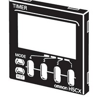
H5CX-B@-N
Nomenclature
1. Key Protection Indicator
2. Control Output Indicator
3. Reset Indicator
4. Present Value Display
5. Time Unit Indicators
6. Set Value
7. Set Value 1, 2 Indicator
Key Protect Level
When the Key-protect Switch is ON, key operations are prohibited
according to the settings for DIP switch pins 6 to 8, thus preventing
setting errors.
The Key-protect Switch can be turned ON and OFF while the power
is ON.
Dimensions
Digital Timers
Digital Timers
H5CX-BWSD-N (Flush Mounting Models)
Dimensions with Flush Mounting Adapter
H5CX-BWSD-N (Provided with Adapter and Waterproof Packing)
Accessories (Order Separately)
Refer to page 12 for details.
Character Size
for Present
Value Display
Lit when the reset input or Reset Key is ON.
Forecast value setting
Absolute value setting
Lit when the reset input or Reset Key is ON.
Character height: 10 mm
If the time range is 0.0 min or 0.0 h, the decimal
point flashes to indicate timing operation.
Character height: 6 mm
Forecast output ON: OUT 1 is lit.
Control output ON: OUT 2 is lit.
Control output 1 ON: OUT 1 is lit.
Control output 2 ON: OUT 2 is lit.
10mm
Display Section
(green)
Character Size
for Set Value
Display
(orange)
6mm
(green)
(red)
(green)
(orange)
(orange)
58
Note: M3.5 terminal screw (effective length: 6 mm)
48×48
48
Y92S-29 (provided)
Waterproof Packing
11
1
2
3
8
9
(51)
7.5
6
Sixth digit
Panel
57.5
59
Y92F-30 (provided)
Flush Mounting Adapter
The Key Protection Indicator is lit orange when the Key-protect Switch
is ON.
If the key protect switch is ON, you will not be able to switch to
Function Setting Mode.
First digit
44.8×44.8
10
12
4
5
6
7
8. Mode Key
9. Reset Key
10. Up Keys 1 to 6
11. Key-protect Switch
12. DIP Switch
Resets present value and output.
(Default setting)
(Changes modes and setting items)
Panel Cutouts
Panel cutouts areas shown below. (according
to DIN43700)
Note: 1. The mounting panel thickness should
OFF
ON
60 min.
2. To allow easier operation, it is
3. It is possible to mount Timers side by
1 2 3 4 5 6 7 8
With Y92A-48F1 attached.
A={48n–2.5+(n–1)×4}
With Y92A-48 attached.
A= (51n–5.5)
be 1 to 5 mm.
recommended that Adapters be
mounted so that the gap between
sides with hooks is at least 15 mm
(i.e., with the panel cutouts separated
by at least 60 mm).
side, but only in the direction without
the hooks. However, if Timers are
mounted side by side, water
resistance will be lost.
15 min.
Operation Key
45
n side by side mounting
(Disabled)
+0.6
–0
A= (48n–2.5)
Switches
OFF
45
A
+0.6
–0
+1
–0
+1
60 min.
–0
(Enabled)
(unit: mm)
ON
–0
+1
Related parts for Y92P-CXT4S
Image
Part Number
Description
Manufacturer
Datasheet
Request
R

Part Number:
Description:
Mounting Hardware Front Panels - Rplc Black (N1.5)
Manufacturer:
Omron
Datasheet:
Part Number:
Description:
Mounting Hardware Front Panels - Rplc Light gray (5Y7/1)
Manufacturer:
Omron
Datasheet:

Part Number:
Description:
PNL CVR LITE GRAY
Manufacturer:
Omron
Datasheet:

Part Number:
Description:
PNL CVR BLACK
Manufacturer:
Omron
Datasheet:
Part Number:
Description:
PNL CVR MED GRAY
Manufacturer:
Omron
Datasheet:

Part Number:
Description:
G6S-2GLow Signal Relay
Manufacturer:
Omron Corporation
Datasheet:
Part Number:
Description:
Compact, Low-cost, SSR Switching 5 to 20 A
Manufacturer:
Omron Corporation
Datasheet:
Part Number:
Description:
Manufacturer:
Omron Corporation
Datasheet:
Part Number:
Description:
Manufacturer:
Omron Corporation
Datasheet:
Part Number:
Description:
Manufacturer:
Omron Corporation
Datasheet:
Part Number:
Description:
Manufacturer:
Omron Corporation
Datasheet: