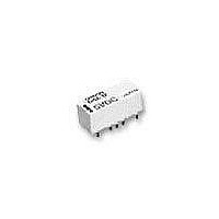
G6Z-1FE-A-DC5 Omron, G6Z-1FE-A-DC5 Datasheet - Page 2

G6Z-1FE-A-DC5
Manufacturer Part Number
G6Z-1FE-A-DC5
Description
Low Signal Relays - PCB NL 5VDC 50 Ohm E terminal 2.6GHz
Manufacturer
Omron
Series
G6Zr
Datasheet
1.G6Z-1FE-A-DC12.pdf
(16 pages)
Specifications of G6Z-1FE-A-DC5
Contact Form
1 Form C
Coil Voltage
5 VDC
Coil Current
40 mA
Coil Type
Non-Latching
Power Consumption
200 mW
Termination Style
Solder Terminal
Isolation
60 dB to 65 dB at 900 MHz / 30 dB to 45 dB at 2.6 GHz
Insertion Loss
0.1 dB to 0.2 dB at 900 MHz / 0.3 dB to 0.5 dB at 2.6 GHz
Maximum Switching Current
0.5 A
Contact Rating
30 V
Current, Rating
10 mA
Function
Frequency (RF)
Mounting Type
PCB
Number Of Pins
9
Power, Rating
10 W
Relay Type
Electro Mechanical
Termination
Surface Mount
Voltage, Control
5 VDC
Voltage, Rating
30 VAC/VDC
Lead Free Status / RoHS Status
Lead free / RoHS Compliant
Available stocks
Company
Part Number
Manufacturer
Quantity
Price
Company:
Part Number:
G6Z-1FE-A-DC5
Manufacturer:
OMRON
Quantity:
3 000
Application Examples
These Relays can be used for switching signals in media equipment.
• Wire communications:
• Wireless communications:
• Entertainment equipment:
• Industrial equipment:
Specifications
■ Contact Ratings
Note: This value is for an impedance of 50 Ω or 75 Ω with a V.S.W.R. of 1.2 max.
■ High-frequency Characteristics
Note: 1. The above values are initial values.
342
Load type
Contact Material
Rated load
Rated carry current
Max. switching voltage
Max. switching current
Isolation
Insertion loss (not
including substrate loss)
V.S.W.R.
Return loss
Maximum carry power
Maximum switching power
Cable TV (STB and broadcasting infrastructure), cable modems, and VRS (video response systems)
Transceivers, ham radios, ETC, ITS, high-level TV, satellite broadcasting, text multiplex broadcasting, mobile phone
stations, TV broadcasting facilities, community antenna systems and car navigation systems
TVs, video games, satellite radio units,
Measuring equipment, test equipment, and multiplex transmission devices
2. These values are for an impedance of 50 Ω or 75 Ω with a V.S.W.R. of 1.2 max.
High-frequency Relay
Terminal structure
Terminal type
75 W
50 W
75 W
50 W
75 W
50 W
75 W
50 W
Frequency
Resistive load
Au clad Cu alloy
10 mA at 30 VAC; 10 mA at 30 VDC; 10 W at 900 MHz (See note)
0.5 A
30 VAC, 30 VDC
0.5 A
65 dB min.
60 dB min.
0.2 dB max.
0.1 dB max.
1.2 max.
1.1 max.
20.8 dB max.
26.4 dB max.
10 W (See note 2)
10 W (See note 2)
G6Z
E-shape
Through hole
Y-shape
900 MHz
60 dB min.
E-shape
Surface mount
Y-shape
35 dB min. 45 dB min. 30 dB min. 40 dB min.
0.5 dB max.
0.3 dB max.
1.5 max.
1.3 max.
14.0 dB max.
17.7 dB max.
E-shape
Through hole
Y-shape
2.6 GHz
E-shape
Surface mount
Y-shape


