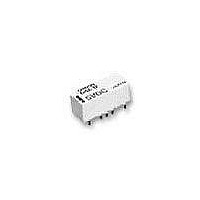
G6Z-1FE-A-DC5 Omron, G6Z-1FE-A-DC5 Datasheet - Page 4

G6Z-1FE-A-DC5
Manufacturer Part Number
G6Z-1FE-A-DC5
Description
Low Signal Relays - PCB NL 5VDC 50 Ohm E terminal 2.6GHz
Manufacturer
Omron
Series
G6Zr
Datasheet
1.G6Z-1FE-A-DC12.pdf
(16 pages)
Specifications of G6Z-1FE-A-DC5
Contact Form
1 Form C
Coil Voltage
5 VDC
Coil Current
40 mA
Coil Type
Non-Latching
Power Consumption
200 mW
Termination Style
Solder Terminal
Isolation
60 dB to 65 dB at 900 MHz / 30 dB to 45 dB at 2.6 GHz
Insertion Loss
0.1 dB to 0.2 dB at 900 MHz / 0.3 dB to 0.5 dB at 2.6 GHz
Maximum Switching Current
0.5 A
Contact Rating
30 V
Current, Rating
10 mA
Function
Frequency (RF)
Mounting Type
PCB
Number Of Pins
9
Power, Rating
10 W
Relay Type
Electro Mechanical
Termination
Surface Mount
Voltage, Control
5 VDC
Voltage, Rating
30 VAC/VDC
Lead Free Status / RoHS Status
Lead free / RoHS Compliant
Available stocks
Company
Part Number
Manufacturer
Quantity
Price
Company:
Part Number:
G6Z-1FE-A-DC5
Manufacturer:
OMRON
Quantity:
3 000
Characteristics
Note: 1. The above values are initial values.
Engineering Data
344
Contact resistance (See note 2)
Operating (set) time (See note 3)
Release (reset) time (See note 3)
Set/reset time
Insulation resistance (See note 4)
Dielectric strength
Vibration resistance
Shock resistance
Service life
Ambient temperature
Ambient humidity
Weight
Ambient Temperature vs.
Maximum Voltage
250
200
150
100
50
0
−40
2. The contact resistance was measured with 10 mA at 1 VDC with a voltage drop method.
3. Values in parentheses are typical values.
4. The insulation resistance was measured with a 500-VDC megohmmeter applied to the same parts as those used for checking the
dielectric strength.
−20
High-frequency Relay
0
20
Item
Ambient temperature (°C)
40
Coil and contacts
Coil and ground,
contacts and ground
Contacts of same
polarity
Mechanical durability
Malfunction durability
Mechanical durability
Malfunction durability
Mechanical
Electrical
60
G6Z
G6ZU
G6ZK
80
100
G6Z
Ambient Temperature vs. Must
Operate or Must Release Voltage
100
90
80
70
60
50
40
30
20
10
0
−60
Sample: G6Z-1P 5 VDC
Number of relays: 5
100 mΩ max.
10 ms max. (approx. 3.5 ms) 10 ms max. (approx. 2.5 ms)
10 ms max. (approx 2.5 ms)
---
100 MΩ min. (at 500 VDC)
1,000 VAC, 50/60 Hz for 1 min.
500 VAC, 50/60 Hz for 1 min.
500 VAC, 50/60 Hz for 1 min.
10 to 55 to 10 Hz, 0.75-mm single amplitude (1.5-mm double amplitude)
10 to 55 to 10 Hz, 0.75-mm single amplitude (1.5-mm double amplitude)
1,000 m/s
500 m/s
1,000,000 operations min. (at 36,000 operations/hour)
300,000 operations min. (30 VAC, 10 mA/30 VDC, 10 mA), 100,000 operations min.
(900 MHz, 10 W) at a switching frequency of 1,800 operations/hour
Operating: -40°C to 70°C (with no icing or condensation)
Operating: 5% to 85% RH
Approx. 2.8 g
−40
G6Z-1P(E), G6Z-1F(E)
−20
Non-latching
2
2
models
0
20
Ambient temperature (°C)
Max. estimated value
40
60
Must operate voltage
Must release voltage
80 100
12 ms
G6ZU-1P(E), G6ZU-1F(E)
max.
max.
avg.
min.
avg.
min.
Single coil latching
Shock direction
Conditions: Shock is applied in ±X, ±Y, and ±Z
Y
Y'
models
Shock Malfunction
1,000
1,000
X
X
Z'
X'
Z
Z'
directions three times each with and
without energizing the Relays to check
for contact malfunctions.
1,000
200
400
600
800
Y
Y'
1,000
800
600
400
200
G6ZK-1P(E), G6ZK-1F(E)
Not
energized
Unit:
Sample: G6Z-1P-A 50 Ω
Number of relays: 5
Dual coil latching
Energized
m/s
5 VDC
models
1,000
1,000
2
Z
X'


