H5CX-A11-DN DC12-24/AC24 Omron, H5CX-A11-DN DC12-24/AC24 Datasheet - Page 22
H5CX-A11-DN DC12-24/AC24
Manufacturer Part Number
H5CX-A11-DN DC12-24/AC24
Description
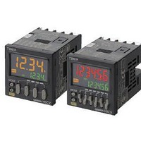
Stopwatches / Timers 11-PIN RELAY OUT Multi-Fnctn
Manufacturer
Omron
Datasheet
1.Y92P-CXT4B.pdf
(44 pages)
Specifications of H5CX-A11-DN DC12-24/AC24
Timing Range
0.001 s to 9999 Hrs
Supply Voltage
12 V to 24 V
Current Rating (max)
100 mA
Display Type
4 Digit LCD Backlight
Product
Digital Timer
Termination Style
Plug In
Lead Free Status / RoHS Status
Lead free / RoHS Compliant
Other names
DC1224/AC24 H5CXA11DN H5CXA11DNDC1224/AC24


22
H5CX-A@-N/-L@-N
Timer
* Start signal input is enabled during timing.
The control output is ON when the start signal is ON
(except when the power is OFF or the reset is ON).
The timer resets when the time is up.
Note: Output functions only during start signal input
* Start signal input is enabled during timing.
Timing starts when the start signal comes ON.
The timer resets when the time is up.
While the start signal is ON, the timer starts when the
power comes ON or when the reset input goes OFF.
Note: Output is disabled when the setting is 0.
Start signal enables timing (timing is stopped when the
start signal is OFF or when the power is OFF).
A sustained control output is used.
Note: Output is instantaneous when setting is 0.
When the H5CX is used with power start in mode F
mode or F-1 (i.e., cumulative operation with output on
hold), there will be a timer error (approximately 100 ms
each time the H5CX is turned ON) due to the
characteristics of the internal circuitry. Use the H5CX
with signal start if timer accuracy is required.
* Start signal input is disabled during timing.
Timing starts when the start signal goes ON.
The status of the control output is reversed when time is
up (ON at start).
While the start signal is ON, the timer starts when power
comes ON or when the reset input goes OFF.
Note: Normal output operation will not be possible if
Mode d: Signal OFF delay (Timer resets when power comes ON.)
Basic operation
Mode E: Interval (Timer resets when power comes ON.)
Basic operation
Mode F: Cumulative (Timer does not reset when power comes ON.)
Basic operation
Mode Z: ON/OFF-duty-adjustable flicker (Timer resets when power comes ON.)
Basic operation
Start signal
Start signal
Start signal
Start signal
Output
Output
Output
Power
Power
Power
Output
Power
input
input
input
when setting is 0.
the set time is too short.
Set the value to at least 100 ms (contact output
type).
input
*
*
*
ON duty
Timing
Timing
(cycle time)
(%)
Timing
Timing
Sustained
Timing
Timing
ON duty
Timing
(cycle time)
(%)
Timing
Detailed operation
Detailed operation
Detailed operation
Detailed operation
Control output
Control output
Control output
Start signal
Start signal
UP
DOWN
UP
DOWN
ON duty setting
ON duty setting
UP
DOWN
Set value
Set value
Set value
Set value
Start signal
Cycle time
(%) ON time
Cycle time
(%) ON time
Power
Power
Reset
Reset
Gate
Gate
Power
Reset
Gate
0
0
0
0
Control output
0
0
Start signal
UP
DOWN
Set value
Set value
Power
Reset
Gate
0
0