H5CX-A11-DN DC12-24/AC24 Omron, H5CX-A11-DN DC12-24/AC24 Datasheet - Page 7
H5CX-A11-DN DC12-24/AC24
Manufacturer Part Number
H5CX-A11-DN DC12-24/AC24
Description
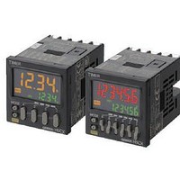
Stopwatches / Timers 11-PIN RELAY OUT Multi-Fnctn
Manufacturer
Omron
Datasheet
1.Y92P-CXT4B.pdf
(44 pages)
Specifications of H5CX-A11-DN DC12-24/AC24
Timing Range
0.001 s to 9999 Hrs
Supply Voltage
12 V to 24 V
Current Rating (max)
100 mA
Display Type
4 Digit LCD Backlight
Product
Digital Timer
Termination Style
Plug In
Lead Free Status / RoHS Status
Lead free / RoHS Compliant
Other names
DC1224/AC24 H5CXA11DN H5CXA11DNDC1224/AC24


Applicable Standards
*1. The following safety standards apply to models with sockets (H5CX-A11@ or H5CX-L8@).
*2. Excluding the H5CX-ASD-N/-A11SD-N/-L8SD-N.
I/O Functions
For details, refer to the timing charts on page 20 and page 29.
*1. The H5CX-L8E@ does not have an input.
*2. The H5CX-L@ does not have a gate input.
Response Delay Time When Resetting (Transistor Output)
The following table shows the delay from when the reset signal is input until the output is turned OFF.
Approved safety standards
EMC
Inputs
Outputs
cUL (Listing): Applicable when an OMRON P2CF (-E) Socket is used.
cUR (Recognition): Applicable when any other socket is used.
Minimum reset signal width
*1
Start signal
Reset
Gate
Control output (OUT)
20 ms
1 ms
*2
UL508/Listing, UL50 Type 4X for indoor use (enclosure rating), CSA C22.2 No. 14
conforms to EN61812-1 (Pollution degree 2/overvoltage category III)
B300 PILOT DUTY
1/4 HP 120 VAC, 1/3 HP, 240 VAC, 5 A resistive load
VDE0106/P100
CCC: Pollution degree 2, Overvoltage category II
(EMI)
Emission Enclosure:
Emission AC mains:
(EMS)
Immunity ESD:
Immunity RF-interference:
Immunity Conducted Disturbance:
Immunity Burst:
Immunity Surge:
Immunity Voltage Dip/Interruption:
Normally functions to start timing.
In modes A-2 and A-3, disable timing. In mode S, starts and stops timing.
• Resets present value. (In elapsed time mode, the present value returns to 0; in remaining time mode,
• Count inputs are not accepted and control output turns OFF while reset input is ON.
• Reset indicator is lit while reset input is ON.
Disables timing. (If a reset occurs while the gate input is ON, a reset will be performed.)
Outputs take place according to designated operating mode when timer reaches corresponding set value.
the present value returns to the set value.)
Output delay time
0.8 to 1.2 ms
15 to 25 ms
(Reference value)
EN61812-1
EN55011 Group 1 class A
EN55011 Group 1 class A
EN61812-1
EN61000-4-2: 6 kV contact discharge (level 2)
EN61000-4-3: 10 V/m (Amplitude-modulated, 80 MHz to 1 GHz) (level 3);
EN61000-4-6: 10 V (0.15 to 80 MHz) (level 3)
EN61000-4-4: 2 kV power-line (level 3);
EN61000-4-5: 1 kV line to lines (power and output lines) (level 3);
EN61000-4-11: 0.5 cycle, 100% (rated voltage)
*2
8 kV air discharge (level 3)
10 V/m (Pulse-modulated, 900 MHz 5 MHz) (level 3)
1 kV I/O signal-line (level 4)
2 kV line to ground (power and output lines) (level 3)
*1
,
H5CX-A@-N/-L@-N
7