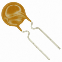
MF-RHT200-2 Bourns Inc., MF-RHT200-2 Datasheet - Page 2

MF-RHT200-2
Manufacturer Part Number
MF-RHT200-2
Description
FUSE PTC RESETTABLE
Manufacturer
Bourns Inc.
Series
MF-RHTr
Type
PTC Resettable Fusesr
Datasheet
1.MF-RHT070-0.pdf
(4 pages)
Specifications of MF-RHT200-2
Voltage - Max
16V
Current - Max
100A
Current - Hold (ih) (max)
2A
Current - Trip (it)
3.8A
R Min/max
0.045 ~ 0.110 Ohm
Time To Trip
3s
Package / Case
Radial
Hold Current
2 Amps
Trip Current
3.8 Amps
Current Rating (max)
100 Amps
Resistance
0.11 Ohms
Maximum Voltage
16 VoltsDC
Termination Style
Radial
Mounting Style
Through Hole
Dimensions
9.4 mm L x 3 mm W x 14 mm H
Lead Spacing
5.1 mm
Operating Temperature Range
- 40 C to + 125 C
Lead Free Status / RoHS Status
Lead free / RoHS Compliant
Lead Free Status / RoHS Status
Lead free / RoHS Compliant, Lead free / RoHS Compliant
Applications
■
■
■
Packaging:
BULK:
TAPE & REEL: MF-RHT070 ~ MF-RHT200 = 3000 pcs. per reel; MF-RHT450 ~ MF-RHT650 = 1500 pcs. per reel;
AMMO-PACK: MF-RHT070 ~ MF-RHT200 = 2000 pcs. per pack; MF-RHT450 ~ MF-RHT750 = 1000 pcs. per pack;
MF-RHT070
MF-RHT200
MF-RHT450
MF-RHT650
MF-RHT750
MF-RHT1300
MF-RHT070
Product Dimensions
Typical Time to Trip at 23 ˚C
Protection of automotive circuitry including engine control modules
Overcurrent surge protection of electronic equipment required to operate at high operating temperature ranges
Resettable fault protection of general electronic equipment
0.01
100
0.1
10
MF-RHT Series - PTC Resettable Fuses
Model
1
Style 1
1
A
500 pcs. per bag
MF-RHT750 ~ MF-RHT1300 = 1000 pcs. per reel
MF-RHT1300 = 500 pcs. per pack
MF-RHT200
C
E
D
B
F
(0.925)
(0.27)
(0.37)
(0.41)
(0.50)
(0.55)
Max.
6.86
10.4
12.7
14.0
23.5
9.4
A
MF-RHT450
Style 2
(0.425)
(0.55)
(0.61)
(0.88)
(0.93)
(1.17)
Max.
10.8
14.0
15.6
22.2
23.5
28.7
B
A
MF-RHT750
MF-RHT650
C
E
B
D
F
(0.201)
(0.201)
(0.201)
(0.201)
(0.201)
(0.402)
Nom.
10.2
5.1
5.1
5.1
5.1
5.1
Fault Cu rrent (Amps)
10
C
MF-RHT1300
Style 3
(0.028)
(0.028)
(0.028)
(0.028)
(0.028)
(0.028)
Tol. ±
0.7
0.7
0.7
0.7
0.7
0.7
A
C
B
D
E
(0.30)
(0.30)
(0.30)
(0.30)
(0.30)
(0.30)
Min.
7.6
7.6
7.6
7.6
7.6
7.6
D
F
Customers should verify actual device performance in their specifi c applications.
(0.12)
(0.12)
(0.12)
(0.12)
(0.12)
(0.14)
Max.
3.0
3.0
3.0
3.0
3.0
3.6
E
Represents total content. Layout may vary.
(0.020)
(0.020)
(0.032)
(0.032)
(0.032)
(0.040)
DATE CODE
(FIRST DIGIT =
LAST DIGIT OF YEAR;
NEXT THREE DIGITS =
DAY OF YEAR)
EXAMPLE: 4180 = 2004 DAY 180
PART
IDENTIFICATION
Nom.
Typical Part Marking
0.51
0.51
0.81
0.81
0.81
1.0
Specifi cations are subject to change without notice.
F
0.51 (24AWG)
0.81 (20AWG)
1.0 (18AWG)
100
MF-RHT SERIES, REV. E, 01/10
The Time to Trip curves represent
typical performance of a device in
a simulated application environment.
Actual performance in specifi c
customer applications may differ
from these values due to the
infl uence of other variables.
Physical Characteristics
Style
1
3
2
2
2
2
RH750
4180S
DIMENSIONS:
MANUFACTURER'S
TRADEMARK
COUNTRY OF
MANUFACTURE
(S = CHINA)
Sn/CuFe
Material
Sn/Cu
Sn/Cu
Sn/Cu
Sn/Cu
Sn/Cu
(INCHES)
MM


