MC13892JVL Freescale Semiconductor, MC13892JVL Datasheet - Page 45
MC13892JVL
Manufacturer Part Number
MC13892JVL
Description
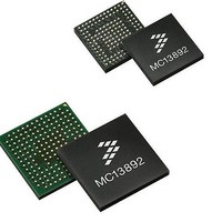
IC PMU I.MX51/37/35/27 186MAPBGA
Manufacturer
Freescale Semiconductor
Datasheets
1.MC13892AJVLR2.pdf
(156 pages)
2.MC13892AJVLR2.pdf
(2 pages)
3.MC13892AJVLR2.pdf
(16 pages)
4.MC13892JVL.pdf
(161 pages)
Specifications of MC13892JVL
Applications
Battery Management, Display (LED Drivers), Handheld/Mobile Devices, Power Supply
Operating Temperature
-40°C ~ 85°C
Mounting Type
Surface Mount
Package / Case
186-LFBGA
Output Current
65 mA
Output Voltage
1.5 V
Operating Temperature (max)
85C
Operating Temperature (min)
-40C
Mounting
Surface Mount
Package Type
BGA
Case Length
12mm
Screening Level
Industrial
Lead Free Status / RoHS Status
Lead free / RoHS Compliant
Current - Supply
-
Voltage - Supply
-
Lead Free Status / Rohs Status
Lead free / RoHS Compliant
Available stocks
Company
Part Number
Manufacturer
Quantity
Price
Company:

Part Number:
MC13892JVL
Manufacturer:
DALSA
Quantity:
4
Company:
Part Number:
MC13892JVL
Manufacturer:
Freescale Semiconductor
Quantity:
10 000
Part Number:
MC13892JVL
Manufacturer:
FREESCALE
Quantity:
20 000
Company:
Part Number:
MC13892JVLR2
Manufacturer:
Freescale Semiconductor
Quantity:
10 000


I
described for SPI access. The MC13892 can function only as an I
for bus conflict avoidance, pin programmable selection is provided through the MOSI pin to allow configuration for the address
LSB(s). This product supports 7-bit addressing only; support is not provided for 10-bit or General Call addressing.
operation. Timing diagrams, electrical specifications, and further details can be found in the I
the number of bytes per transfer is unrestricted. The register map of the MC13892 is organized in 24 bit registers which
corresponds to the 24 bit words supported by the SPI protocol of this product. To ensure that the I
transactions in behavior of a complete 24 bit word being written in one transaction, software is expected to perform write
transactions to the device in 3 byte sequences, beginning with the MSB. Internally, data latching will be gated by the acknowledge
at the completion of writing the third consecutive byte.
could be due to a premature STOP command from the master.
and 3 bytes will be sent out, unless a STOP command or NACK is received prior to completion.
host sends a master command packet after driving the start condition. The device will respond to the host if the master command
packet contains the corresponding slave address. In the following examples, the device is shown always responding with an ACK
to transmissions from the host. If at any time a NAK is received, the host should terminate the current transaction and retry the
transaction.
I
addressing for bus conflict avoidance, pin programmable selection is provided to allow configuration for the address LSB(s). This
product supports 7-bit addressing only. Support is not provided for 10-bit or General Call addressing.
hardwiring to VCORE or GND at the board level, when configured for I
address assigned to FSL PM ICs (shared amongst our portfolio) is as follows:
FSL PM ICs on a given board, which could be sharing an I
LSB A0 for board level configuration. The A1 bit will be implemented such that it can be re-wired as a “1” (with a metal change
or fuse trim), if conflicts are encountered before the final production material is manufactured. The designated address is defined
as: 000100-A0.
I
operation. The exceptions to the standard are noted to be 7-bit only addressing, and no support for General Call addressing.
Timing diagrams, electrical specifications, and further details can be found in the I
download at:
number of bytes per transfer are unrestricted. The register map is organized in 24 bit registers, which corresponds to the 24 bit
words supported by the SPI protocol of this product. To ensure that I
complete 24 bit word being written in one transaction. The software is expected to perform write transactions to the device in 3
byte sequences, beginning with the MSB. Internally, data latching will be gated by the acknowledge at the completion of writing
the third consecutive byte.
could be due to a premature STOP command from the master, for example. I
Analog Integrated Circuit Device Data
Freescale Semiconductor
2
2
2
C CONFIGURATION
C DEVICE ID
C OPERATION
When configured for I
I
The I
Standard I
Failure to complete a 3 byte write sequence will abort the I
I
The following examples show how to write and read data to the IC. The host initiates and terminates all communication. The
The I
Because the MOSI pin is not utilized for I
00010-A1-A0, where the A1 and A0 bits are allowed to be configured for either 1 or 0. It is anticipated for a maximum of two
The I
http://www.nxp.com/acrobat_download/literature/9398/39340011.pdf
Standard I
Failure to complete a 3 byte write sequence will abort the I
2
2
C interface protocol requires a device ID for addressing the target IC on a multi-device bus. To allow flexibility in addressing
C read operations are also performed in byte increments separated by an ACK. Read operations also begin with the MSB
2
2
2
C mode of the interface is implemented generally following the Fast Mode definition which supports up to 400 kbits/s
C interface protocol requires a device ID for addressing the target IC on a multi-device bus. To allow flexibility in
C mode of the interface is implemented, generally following the Fast mode definition, which supports up to 400 kbits/s
2
2
C protocol utilizes packets of 8 bits (bytes), with an acknowledge bit (ACK) required between each byte. However,
C protocol utilizes bytes of 8 bits, with an acknowledge bit (ACK) required between each byte. However, the
2
C mode (see
Table
2
C communication, it is reassigned for pin programmable address selection by
7) the interface may be used to access the complete register map previously
I
2
C INTERFACE
2
C bus. The A1 address bit is internally hardwired as a “0”, leaving the
2
2
C transaction and the register will retain its previous value. This
C transaction, and the register will retain its previous value. This
2
C slave device, not as a host.
2
C operation mimics SPI transactions in behavior of a
2
C mode. MOSI will act as Bit 0 of the address. The I
2
C read operations are also performed in byte
2
C specification, which is available for
2
C specification.
FUNCTIONAL DEVICE OPERATION
2
C operation mimics SPI
I2C INTERFACE
13892
2
45
C
Related parts for MC13892JVL
Image
Part Number
Description
Manufacturer
Datasheet
Request
R


Part Number:
Description:
Manufacturer:
Freescale Semiconductor, Inc
Datasheet:
Part Number:
Description:
Manufacturer:
Freescale Semiconductor, Inc
Datasheet:
Part Number:
Description:
Manufacturer:
Freescale Semiconductor, Inc
Datasheet:
Part Number:
Description:
Manufacturer:
Freescale Semiconductor, Inc
Datasheet:
Part Number:
Description:
Manufacturer:
Freescale Semiconductor, Inc
Datasheet:
Part Number:
Description:
Manufacturer:
Freescale Semiconductor, Inc
Datasheet:
Part Number:
Description:
Manufacturer:
Freescale Semiconductor, Inc
Datasheet:
Part Number:
Description:
Manufacturer:
Freescale Semiconductor, Inc
Datasheet:
Part Number:
Description:
Manufacturer:
Freescale Semiconductor, Inc
Datasheet:
Part Number:
Description:
Manufacturer:
Freescale Semiconductor, Inc
Datasheet:
Part Number:
Description:
Manufacturer:
Freescale Semiconductor, Inc
Datasheet:
Part Number:
Description:
Manufacturer:
Freescale Semiconductor, Inc
Datasheet:
Part Number:
Description:
Manufacturer:
Freescale Semiconductor, Inc
Datasheet: