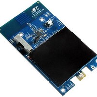
ENERGY-HARVEST-RD Silicon Laboratories Inc, ENERGY-HARVEST-RD Datasheet - Page 3

ENERGY-HARVEST-RD
Manufacturer Part Number
ENERGY-HARVEST-RD
Description
RD ENERGY HARVESTING
Manufacturer
Silicon Laboratories Inc
Type
Energy Harvestingr
Datasheet
1.ENERGY-HARVEST-RD.pdf
(12 pages)
Specifications of ENERGY-HARVEST-RD
Output Voltage
4.1 V
Interface Type
USB
Output Current
50 nA
Product
Power Management Development Tools
Lead Free Status / RoHS Status
Lead free / RoHS Compliant
For Use With/related Products
Si1012
Other names
336-2047
Available stocks
Company
Part Number
Manufacturer
Quantity
Price
Company:
Part Number:
ENERGY-HARVEST-RD
Manufacturer:
SiliconL
Quantity:
13
4. Software Setup
The Energy Harvesting demo application is designed for the Windows operating systems and is distributed as part
Wireless Development Suite (WDS). The Wireless Development Suite may be downloaded from the following web
page:
http://www.silabs.com/MCUDownloads
Once WDS is downloaded from the Silicon Labs website, extract the executable from the zip file and run it to install
the Wireless Development Environment. Program shortcuts are also added to the Start Menu under the Silicon
Laboratories folder.
5. Energy Harvesting Demo
The Energy harvesting demo shows how an energy harvesting sensor node can periodically transmit data to the
PC. To run the demo, first ensure that the software is installed as described in “4. Software Setup” and that the
EZRadioPRO dongle is plugged into a USB port on the PC.
1. Launch the program, which is found by clicking StartAll ProgramsSilicon LaboratoriesWDS3.
2. Select Harvesting Demo
3. Go through the on-screen menu until the Harvesting Demo Application appears.
4. The Energy Harvesting Demo Application is now ready to receive information from the sensor node.
5. Place the S2 power source switch in the SOLAR position. It takes 15 to 30 seconds for the sensor node to
charge a 100 µF capacitor from the solar cell (200 lx minimum), then use the stored energy for a full POR. The
green LED should blink 3 times to indicate that the sensor node is powered up. Three red LED blinks indicate
that there is not enough energy in the system to start up, and that the sensor node needs to be charged. A
combination of green and red blinks indicates that the system has enough energy to start up, but the stored
energy level is below 75% of its maximum capacity.
Figure 4. Energy Harvesting Demo Application Initial Screen
Rev. 0.2
AN588
3


