XRP7708EVB Exar Corporation, XRP7708EVB Datasheet - Page 13
XRP7708EVB
Manufacturer Part Number
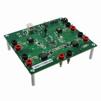
XRP7708EVB
Description
EVAL BOARD FOR XRP7708
Manufacturer
Exar Corporation
Type
PMIC Solutionsr
Specifications of XRP7708EVB
Main Purpose
DC/DC, Step Down
Outputs And Type
*
Voltage - Output
*
Current - Output
*
Voltage - Input
*
Regulator Topology
Buck
Frequency - Switching
*
Board Type
Fully Populated
Utilized Ic / Part
XRP7708
Board Size
6 mm x 6 mm x 0.8 mm
Interface Type
I2C
Maximum Operating Temperature
+ 125 C
Operating Supply Voltage
6.5 V to 20 V
Product
Power Management Development Tools
Sense Voltage (max)
5 mV
Dimensions
6 mm x 6 mm x 0.8 mm
Silicon Manufacturer
Exar
Silicon Core Number
XRP7708
Kit Application Type
Power Management - Voltage Regulator
Application Sub Type
Step Down DC/DC Controller
For Use With/related Products
XRP7708
Lead Free Status / RoHS Status
Lead free / RoHS Compliant
Power - Output
-
Lead Free Status / RoHS Status
Lead free / RoHS Compliant
Other names
1016-1346


I
When the ENABLE pin is set, internal VCC and VDD power up upon the power up of VIN1. Once the
bandgap reference is stable and VCC and VDD fall into the acceptable range, an internal VDDOK
flag is generated. A SYS_RESET remains low for a few clock cycles to reset all the internal
registers. After that the internal CONFIGURATION_TRANSFER signal raises high and the chip
transits to the second phase.
C
In this phase, the contents in the configuration memory are transferred to the internal registers.
The internal oscillator switches to the programed switching frequency. The GPIO pins are properly
configured as either inputs or outputs. If the chip is programmed to run in the I
and GPIO5 are configured to serve as SDA and SCL for the I
the NON-I
C
In this phase, the chip is ready for normal operation. An internal CHIP_READY flag goes high and
enables the I
always-on channels are enabled. Channels that are configured to be enabled by GPIOs are also
enabled if the respective GPIO is asserted.
S
This 100mA low drop-out regulator can be programmed as 3.3V or 5V in SET_STBLDO_EN_CONFIG
register. Its output is seen on the LDOOUT Pin. This LDO is fully controllable via the Enable Pin
(configured to turn on as soon as power is applied), a GPIO, and/or I
E
The XRP7708 is enabled via raising the ENABLE Pin high.
lowering the same ENABLE Pin.
SOFTRESET Command.
For enabling a specific channel, there are several ways that this can be achieved. The chip can be
configured to enable a channel at start-up as the default configuration residing in the non-volatile
configuration memory of the IC. The channels can also be enabled using GPIO pins and/or an I
© 2010 Exar Corporation
NTERNAL
ONFIGURATION
HIP
TANDBY
NABLING
R
EADY
2
L
, D
C mode, then these two pins can be used as GPIO4 and GPIO5 respectively.
LDO P
OW
P
ISABLING AND
2
C to acknowledge the Host’s serial commands. Channels that are configured as
HASE
D
ROP
T
OWER
RANSFER
– P
-
ENABLE_PIN
VIN1
VCC
VDD
VDDOK
SYS_RESET
CONFIG_TRANSFER
CHIP_READY
OUT
-U
HASE
P
R
P
EGULATOR
P
R
HASE
3
HASE
ESET
Phase 1
Q
Q
There is also the capability for resetting the Chip via an I
– P
u
u
– P
a
a
Fig. 17: Power Up Sequence
d
d
HASE
HASE
C
C
h
h
a
a
1
2
13/27
n
n
Phase 2
n
n
e
e
l
l
D
D
i
i
g
g
i
i
t
t
2
a
a
C bus. If chip is programmed to run in
l
l
Phase 3
P
P
The chip can then be disabled by
W
W
M
M
2
C communication.
S
S
t
t
e
e
p
p
D
D
o
o
w
w
2
n
C mode, GPIO4
n
X
X
C
C
R
R
o
o
n
P
n
P
Rev. 1.0.3
t
t
7
7
r
r
o
7
o
7
l
l
0
0
l
l
e
e
2
2
8
8
C
C
r
r
Related parts for XRP7708EVB
Image
Part Number
Description
Manufacturer
Datasheet
Request
R

Part Number:
Description:
Quad Channel Digital Pwm Step Down Controller
Manufacturer:
Exar Corporation
Datasheet:
Part Number:
Description:
BiCMOS Fixed, Quad, Voltage Output, Single or Dual Supply 8-Bit Digital-to-Analog Converter
Manufacturer:
Exar Corporation
Datasheet:
Part Number:
Description:
Manufacturer:
Exar Corporation
Datasheet:
Part Number:
Description:
Voltage-Controlled Oscillator
Manufacturer:
Exar Corporation
Datasheet:
Part Number:
Description:
INTEGRATED LINE TRANSMITTER
Manufacturer:
Exar Corporation
Datasheet:
Part Number:
Description:
Monolithic Function Generator
Manufacturer:
Exar Corporation
Datasheet:
Part Number:
Description:
CMOS Microprocessor Compatible Double-Buffered 12-Bit Digital-to-Analog Converter
Manufacturer:
Exar Corporation
Datasheet:
Part Number:
Description:
CMOS 6 BIT HIGH SPEED ANALOG TO DIGITAL CONVERTER
Manufacturer:
Exar Corporation
Datasheet:
Part Number:
Description:
Manufacturer:
Exar Corporation
Datasheet:
Part Number:
Description:
Manufacturer:
Exar Corporation
Datasheet:
Part Number:
Description:
8-Channel, Voltage Output 10 MHz Input Bandwidth 8-Bit Multiplying DACs with Serial Digital Data Por
Manufacturer:
Exar Corporation
Datasheet:
Part Number:
Description:
15 V CMOS Multiplying10-Bit Digital-to-Analog Converter
Manufacturer:
Exar Corporation
Datasheet:
Part Number:
Description:
Monolithic Function Generator
Manufacturer:
Exar Corporation
Datasheet: